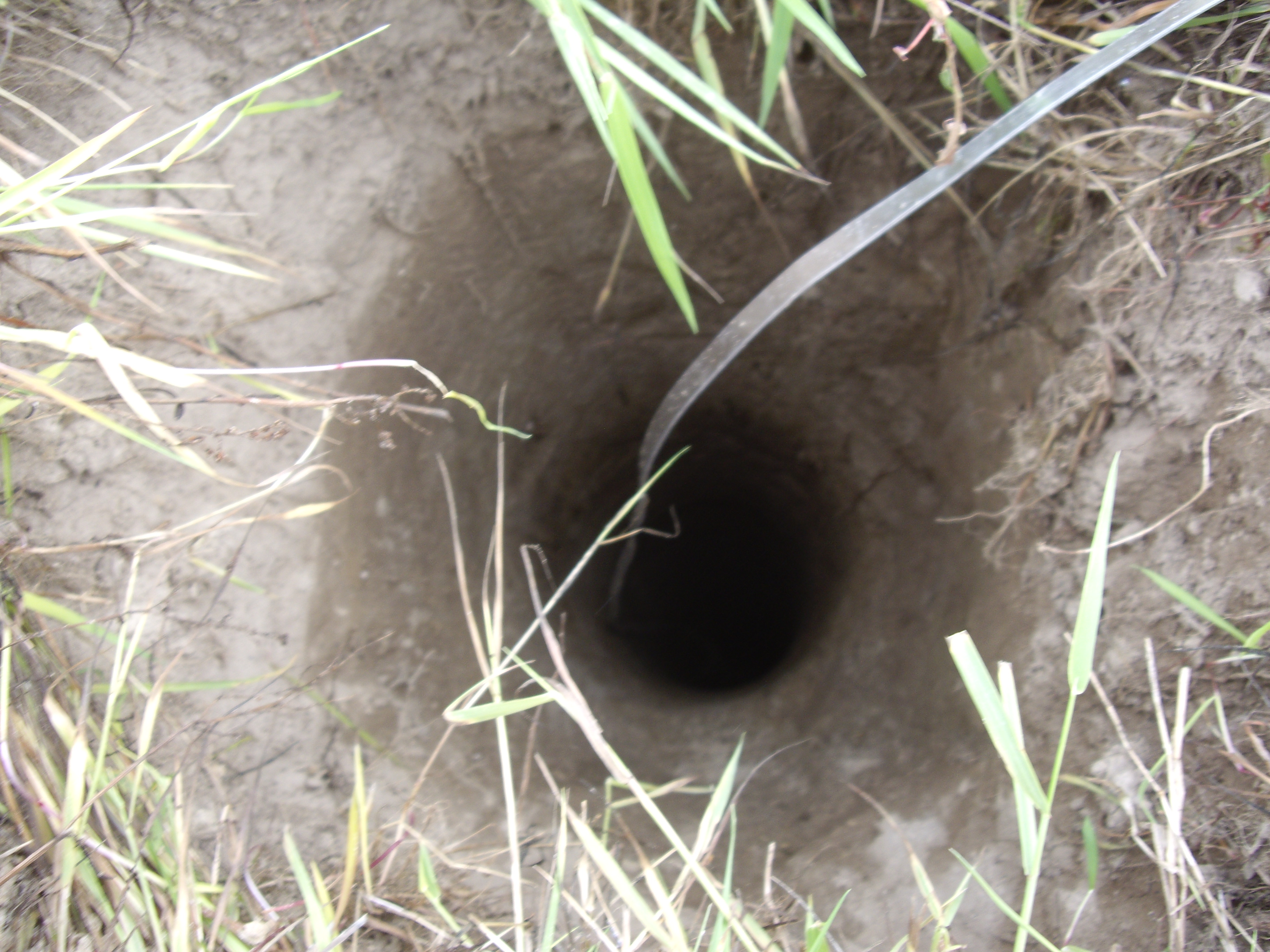
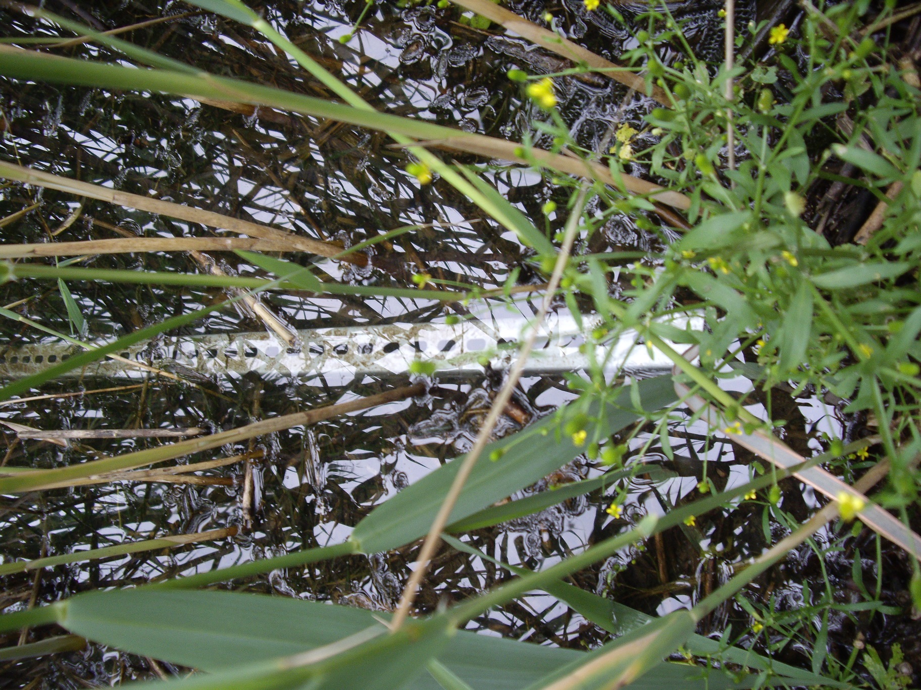
I conducted my first tests with earth electrode antenna in the nineties with the use of hot water installation. While drilling a well on my piece of land in the countryside I thought this could be just the right moment to explore this idea a bit more. A test drill for 5 meters provided a hole where I put an electrode. However, the soil in the hole was utterly dry and the electrode was not covered with it – it was just a two meters long aluminium L-beam. High resistance of this connection apparently influenced the antenna’s efficiency. A steel beam with ‘L’ cross section immersed in the water on the shore of a small lake served as the other electrode. The distance between the two electrodes was ca. 150 meters.
An electrode placed in the test-drilled hole.
An electrode placed by a lakeshore.
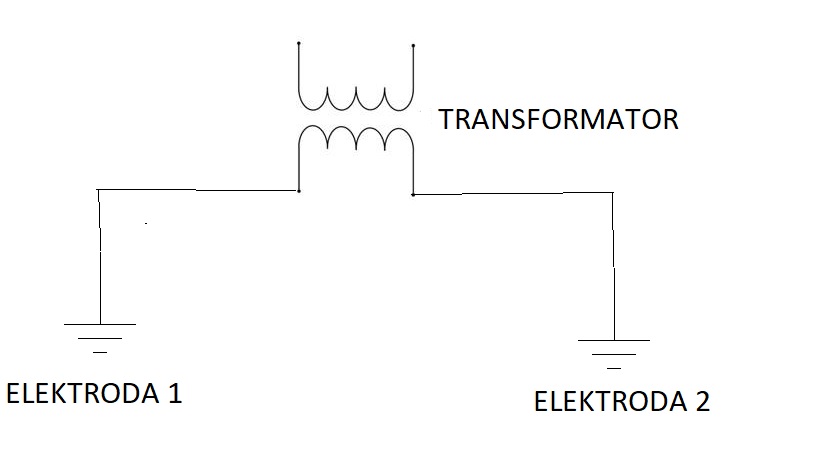
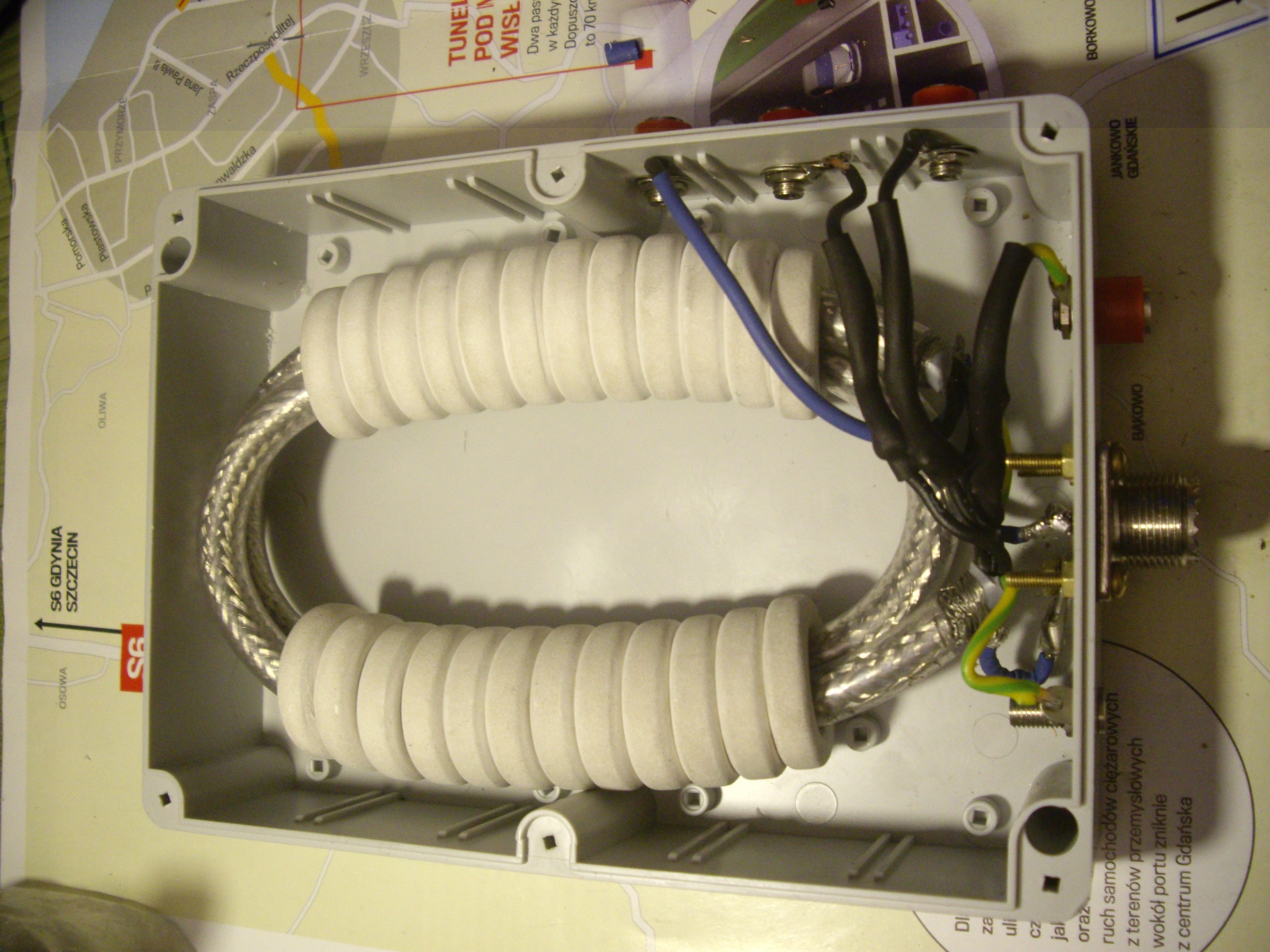
To complete the entire construction I used an experimental transformer with ratio 1:1, 1:4, 1:9 i 1:16. The approximate impedance of the antenna on 150kHz was 800 Ohm (ratio 1:16) and on 500kHz this was approx. 400 Ohm (ratio 1:9).
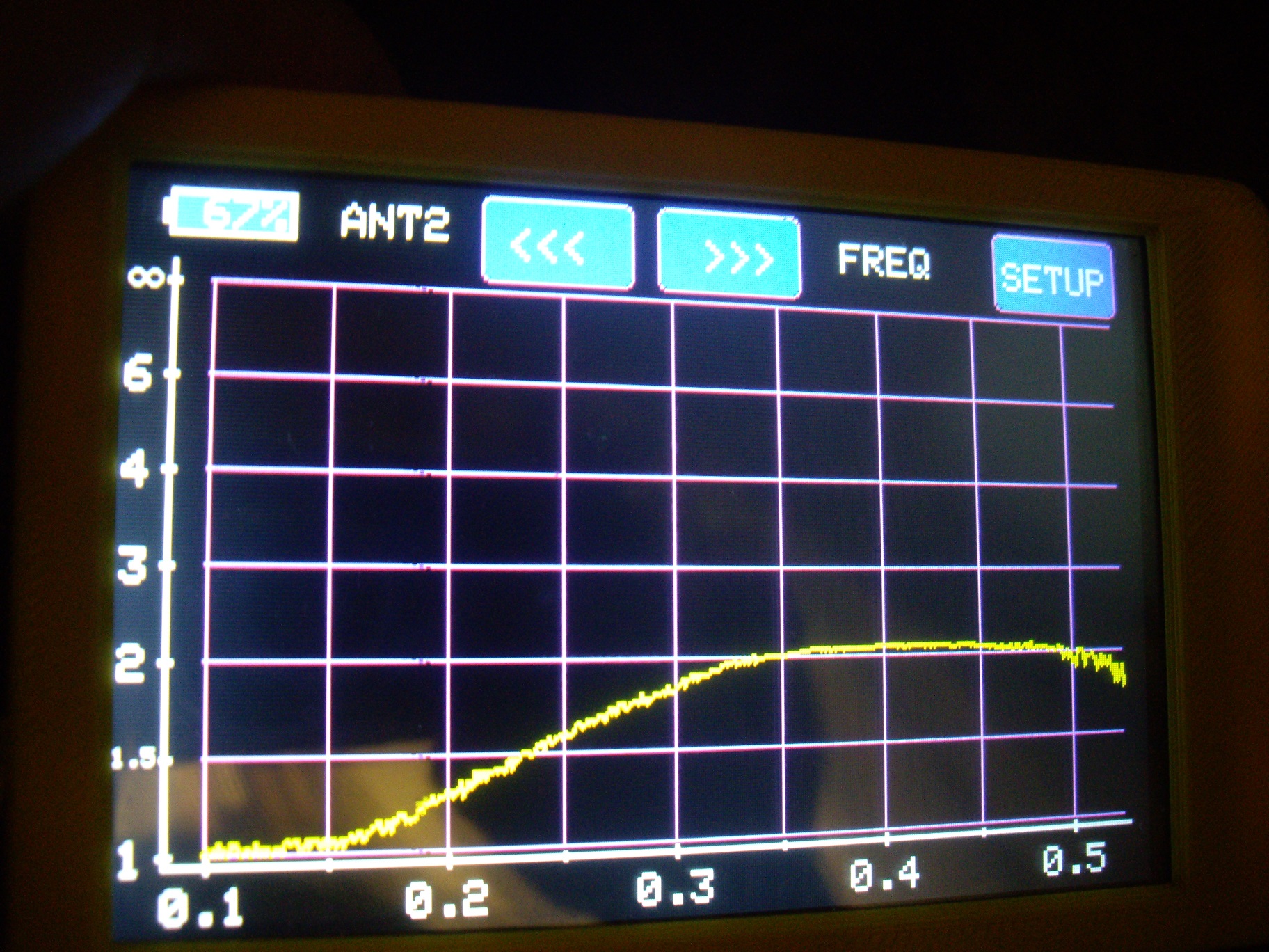
Antenna analyser measurement according to SQ1GU with an option of work under 1MHz ratio 1:9
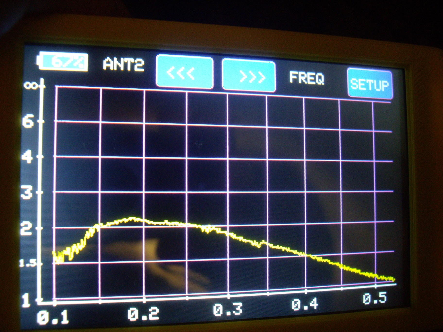
Antenna analyser measurement according to SQ1GU with an option of work under 1MHz (ratio 1:16)
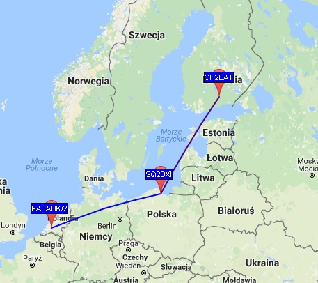
ID-Elektronik SWR-meter (135kHz-10MHz) measured the standing wave ratio in 472kHz was ca. 1,5, which allowed for successful tests of transmission and receipt in 630 m. Significant QRN of the approaching summer was the cause of small 472kHz activity but it allowed my signal to be received in Finland (OH2EAT) and I managed to receive signals from the Netherlands (PA3ABK/2) in WSPR mode.
In the movie below you will see the difference in receipt of long and medium waves by a 20 meters-long wire antenna and an earth electrode antenna