Simple setup for monitoring of VLF signals using vlfrx-tools
Paul Nicholson’s vlfrx-tools are one of the tools of choice when doing VLF monitoring and analysis. This article shows an example of a simple setup used for VLF monitoring and ebnaut decoding. The sound card sample rate is compensated using a 1PPS signal source froma GPS receiver. A description of a simple 1PPS distribution amplifier is here: Simple 1PPS signal source and distribution amplifier
The phase of signals received in the VLF band can often be stable even over large distances. This enables receiving very weak signals if the transmitter and receiver have very good frequency stability. A 1PPS signal can be used as the reference. This enables analysis of signals in the 10kHz range with resolution on the 1uHz order of magnitude.
There will be a separate article detailing how to use vlfrx-tools with this hardware setup on the klubnl.pl website.
Hardware description
A simplified diagram of the setup is presented in Fig 1, the main blocks are:
- a computer with Debian/GNU Linux 8
- a Creative EMU-0204 external sound card (an internal card could also be used with some modifications)
- a VLF active antenna, in this case it’s a modifier PA0RDT mini-whip
- a GPS receiver with a distribution amplifier, and a simple optical isolation and pulse forming circuit
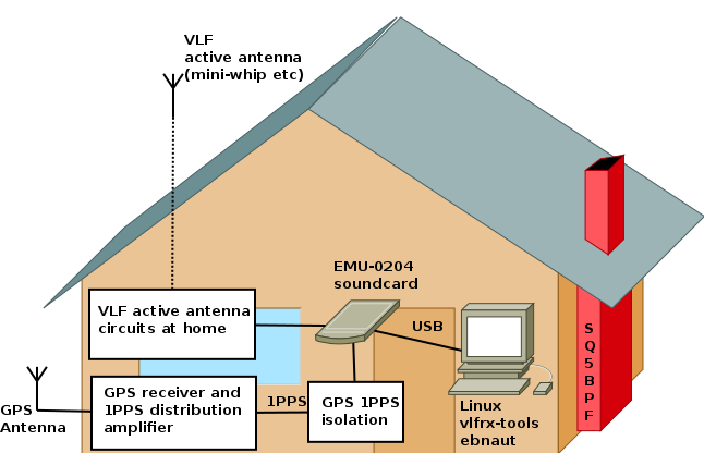
Fig 1. Simplified block diagram
The 1PPS signal source is described in: Simple 1PPS signal source and distribution amplifier
The connection to the sound card is presented in Fig 2.
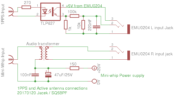
Fig 2. Sound card interface
The 1PPS signal is fed into the L soundcard input. This signal is used to correct the soundcard sample rate, and any interference to this signal (such as 50Hz in case of ground loops etc) will cause problems with stability. To avoid this the signal is passed via an optio-isolator. The signal is then passed into a pulse shaping RC network and into the L soundcard input. The +5V supply is taken from the soundcard input. In case of other soundcards the supply can be tapped from the card, from an external power supply or from a battery.
The receive antenna is a modified PA0RDT mini-whip, with a 50cm piece of wire for the e-field probe (this antenna will be described in a separate article). The antenna is powered from a 20V power supply via a RC filter. The output signal is coupled via an audio transformer (from a modem or some other phone equipment) to the soundcard R input. Galvanic isolation from the sound card input stops interference from the sound card ground (50Hz, power supply noise etc) from entering the antenna ground. These are not only 50Hz and harmonics, but also wideband hiss, which can lower the S/N considerably.
Setting it up
The main problem with VLF reception is powerline noise (and harmonics). During the initial setup it’s recommended to run as much of the equipment as possible on batteries (laptop battery, battery power for the antenna etc). This gives the lowest noise floor, so that later the effects of swapping the batteries for power supplies can be observed. You should also use the best possible grounding if a e-field antenna is used.
The EMU-0204 sound card Karta dźwiękowa EMU-0204 has separate gain controls for the L and R inputs. Every input has two LED indicators: green which signals that the input is above -12dB relative to the full ADC input range, and red which signals clipping (the input is over the ADC range).
The L input gain should be set so that the 1PPS signal has an amplitude of approximately 80% of the ADC range. The R input gain should be set so that the input signal is high, but so that clipping doesn’t occur often (it can occur when receiving strong sferics etc).
The use of vlfrx-tools with this setup will be described in another article.
Author: Jacek SQ5BPF