The plot thickens!
The square wave isn't exactly symmetrical but by that calculation it
makes no more than 8 watts into the dummy load without the filter!
It's likely a bit more because it isn't symmetrical, but nowhere
near the 25 watts I get with the filter. Hmm...
Paul N1BUG


On 12/24/2017 05:42 PM, Andy Talbot wrote:
Well ... Using exactly the values in the filter circuit diagram,
50R transforms through the filter to 48.5 - j2.86 (Ret Loss = 30dB,
VSWR = 1.07) [Using GM3SEK's original Netcalc prog.]
So that's pretty conclusive the ideal filter values will not be
upsetting things at the fundamental frequency.
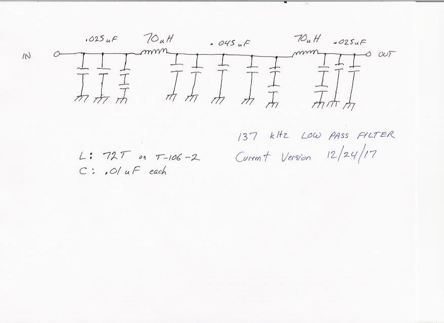
According to Google, the T106-2 has a stated Al value of 13.5nH
/turn^2 so 72 turns does indeed give 70uH. So IF your core is
correct, the filter should be OK.
It's a bit difficult from now on, at a distance, to try to work out
what is happening.
Anyone else, any suggestions ?

BTW ...
Peak to peak of a { symetrical }square wave needs to be multiplied
by 4/pi to get the peak-to-peak of the fundamental component. So
the amploitude you see will be lower by about 1.3 times for teh same
fundamental power component.
Andy G4JNT
On 24 December 2017 at 21:22, N1BUG <[email protected]
<mailto:[email protected]>> wrote:
Hi Andy,
Thank you very much for that. I am learning and knowledge
sometimes comes together from bits and pieces in discussions
like this.
Anything is possible with this amp or the filter.
I tried without the filter but as it is now a somewhat spiky
square wave I have no idea how it compares power-wise. It did
appear to be lower. Except for a short spike at the leading edge
of the positive pulses the pk-pk amplitude was much less than
with the filer.
This is the filer, for what it's worth:
http://n1bug.com/n1debug/ASB_LF_LPF-20171224.jpg
<http://n1bug.com/n1debug/ASB_LF_LPF-20171224.jpg>
You may have helped me understand something I saw the other day.
One of the .01 capacitors on the output end of the filter became
disconnected and I saw more power out of the amp. Perhaps that
was due to an impedance change.
Paul N1BUG
On 12/24/2017 03:44 PM, Andy Talbot wrote:
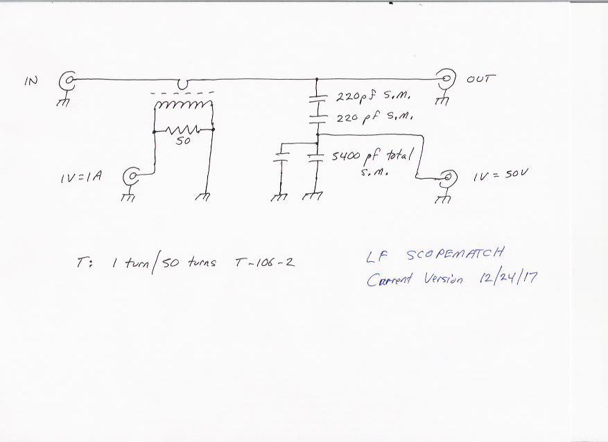
The scopematch circuit looks reasonable. Arithmetic is correct
(as an aside, I always group constants together for
calibrations like that. Measuring peak to peak across a
50R load, power then becomes Vpk-pk ^ 2 / 400
When my 30dB power attenuator is in circuit this becomes P =
2.5 Vp-p ^ 2 You could do the same grouping and
simplifying for your scopematch dividers and Vp-p readings)
Back to your amp ...
You get 25W into 50R going via the low pass filter
You don't show your low pass filter circuit.
It is possible that has the wrong values for 50R and is
providing an impedance transformation from your 50R true
load to present the amplifier with a lower RL, thus allowing
more output
Terminate the amplifier directly with the 50 ohs load and
see what you get - so eliminating the filter
As Sherlock Holmes said "Once you have eliminated the
impossible, whatever remains, however improbable, must be so"
Andy G4JNT
On 24 December 2017 at 20:12, N1BUG <[email protected]
<mailto:[email protected]> <mailto:[email protected]
<mailto:[email protected]>>> wrote:
Hi Andy,
This is very interesting, because 12 watts is what I
think I
have consistently been able to generate into the
antenna before
problems creep in.
I can easily accept that this amplifier may only be
capable of
12 or 13 watts.
What I don't understand is why I think I am seeing a
clean 25
watts into a pure resistive 50 ohm load. Can someone please
check my math?
I'm running the output of the amplifier through a low pass
filter, then a scopematch, then into a high quality 50
ohm load.
My scopematch circuit is here:
http://n1bug.com/n1debug/LF_ScopeMatch-20171224.jpg
<http://n1bug.com/n1debug/LF_ScopeMatch-20171224.jpg>
<http://n1bug.com/n1debug/LF_ScopeMatch-20171224.jpg
<http://n1bug.com/n1debug/LF_ScopeMatch-20171224.jpg>>
Note that it is configured such that on the current sense
output, 1V=1A and for voltage, 1V=50V.
Running into a pure 50 ohm resistive load I am seeing
exactly 4
divisions peak to peak on the scope (2 divisions above
center, 2
below).
500 mV/div * 4 divs = 2.0V peak-peak or 0.707V RMS.
0.707 * 50 (1V=50V on the scopematch) = 35.4V RMS.
35.4^2 / 50 ohms = 25 watts.
Where am I going wrong?
As a check on scopematch calibration I set my HP 3325B
to 10V
peak-peak, ran it through the scopematch into the same
50 ohm
dummy load at 137.5 kHz. I set the scope to 50 mV/div
and it
read exactly 4 divisions peak-peak = .2V * 50 = 10V
which seems
to verify. Admittedly this verification is at a much
lower power
level.
73,
Paul N1BUG
|