Hi Andy,
This is very interesting, because 12 watts is what I think I have
consistently been able to generate into the antenna before problems
creep in.
I can easily accept that this amplifier may only be capable of 12 or
13 watts.
What I don't understand is why I think I am seeing a clean 25 watts
into a pure resistive 50 ohm load. Can someone please check my math?
I'm running the output of the amplifier through a low pass filter,
then a scopematch, then into a high quality 50 ohm load.
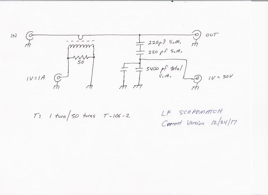
My scopematch circuit is here:

http://n1bug.com/n1debug/LF_ScopeMatch-20171224.jpg
Note that it is configured such that on the current sense output,
1V=1A and for voltage, 1V=50V.
Running into a pure 50 ohm resistive load I am seeing exactly 4
divisions peak to peak on the scope (2 divisions above center, 2 below).
500 mV/div * 4 divs = 2.0V peak-peak or 0.707V RMS.

0.707 * 50 (1V=50V on the scopematch) = 35.4V RMS.

35.4^2 / 50 ohms = 25 watts.

Where am I going wrong?
As a check on scopematch calibration I set my HP 3325B to 10V
peak-peak, ran it through the scopematch into the same 50 ohm dummy
load at 137.5 kHz. I set the scope to 50 mV/div and it read exactly
4 divisions peak-peak = .2V * 50 = 10V which seems to verify.
Admittedly this verification is at a much lower power level.
73,
Paul N1BUG


On 12/24/2017 01:06 PM, Andy Talbot wrote:
The other thing about that circuit that is wrong is the power out
specification for the turns ratio / loading resistance.
For a single ended PA, Pout max = Vdd ^2 / 2 / RL. With a 9:1 (3:1
turns) transformer RL = 50 / 9 = 5.6 ohms
So for a 13.8V suply (ignoring Vsaturation) that means an absolute
maximum power output possible of 13.8^ / 2 / 5.6 = 17 Watts into a
true 50 ohms load on the transformer output.
In practice the device will saturate with a volt or so across it,
lowering the voltage swing and keeping power out to a lower value.
If the peak swing is 12V, Pmax now drops to 12^2/2/5.6 = 13 watts
Riccardo, I assume you mean 1:4 turns ratio, or 1:16 impedance
transformation. That Means RL = 50/16 = 3.1 ohms and at 12V swing
gives 23 watts out as you state
I made a push-pull PA using a similar type of FET, but used a 28V
supply and 1+1:2 transformer. It gives 40 - 50 Watts over the
frequency range 100kHz to 2MHz
http://www.g4jnt.com/Linear_LF_PA3.pdf

Andy  G4JNT
On 24 December 2017 at 17:33, Riccardo Zoli
<[email protected] <mailto:[email protected]>> wrote:
    Hi Paul, Stefan

    my first PA for MF and LF, based on a IRF520, was similar.
    However, I used a most appropriate 1:4 output transformer
    instead a 1:9. With 13.8V, a 50mA bias current is more than
    adequate for AB class. You could obtain about 20-22W max on output.
    Obiviously, more supply voltage it means more power output.

    Merry XMAS & HNY!

    All the best


    73 de Riccardo IW4DXW


    Il 24/Dic/2017 13:30, "DK7FC" <[email protected]
    <mailto:[email protected]>> ha scritto:

        Hi Paul,

        Am 23.12.2017 23 <tel:23.12.2017%2023>:36, schrieb N1BUG:

            For anyone trying to follow along, this is my current
            version:

            http://n1bug.com/ASB_LF_Amp-20171223.jpg
            <http://n1bug.com/ASB_LF_Amp-20171223.jpg>


        The circuit looks good to me now. Maybe it helps to use a
        low pass filter in T configuration instead of a PI config.
        The T config starts with a series L. The PI config starts
        with a parallel C. That could make a significant difference
        for the harmonics.

        73 and Merry christmas, Stefan
|