HAMs often need to use compromise antennas, which they try to force into use on as many bands as possible. A longwire is an often used antenna – the antenna wire between buildings doesn’t attract unneded attention as long as it doesn’t have any distinctive features (such as in a dipole).
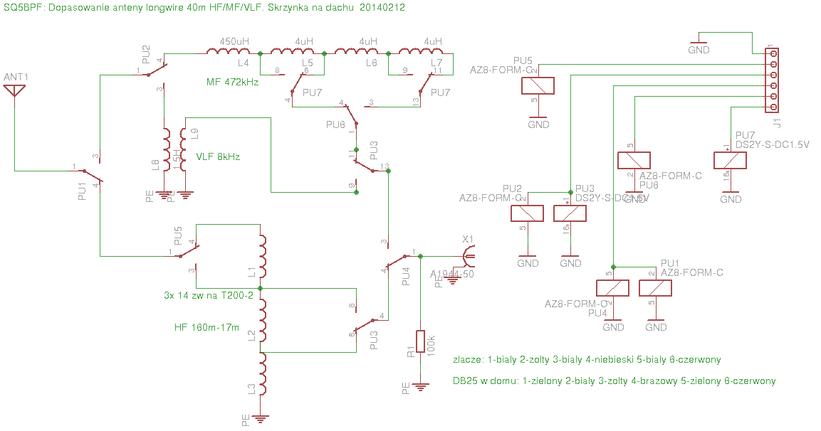
I live in a typical concrete apartament building, which limits instalation of large antennas. For a long time the only antenna i had was a 40m longwire between two 5-story buildings. This antenna has to be enough for all HF bands 160-17m, for 630m and for VLF. For this reason i installed a multiband matching circuit on the roof, remotely operated via relays.

The relays switch the longwire between a matching transformer for all bands 160-17m. The ratios are 1:1, 4:9, 1:4 and 1:9. This is 14 windings trifilar on an Amidon T200-2 core.
There is a transformer for VLF. This is from an old TV HV circiut. The secondary is resonant with the 200pF antenna capacitance at around 8kHz. The primary winding is 10 turns.
There is also a coil for 630m, with additional coils switch in series to allow fine tuning. To achieve a small size, the main coil is wound on a large ferrite rod. This is called an impeder rod, and is used in induction welding of pipes.
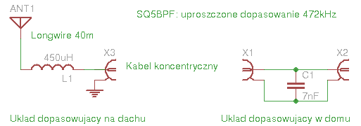
A series coil matching circiut has the disadvanvage that there is no control of the impedance. My antenna had 12 ohms at resonance. Further matching is done by a 7nF capacitor to ground, which is connected not on the roof, but at the other end of the coax cable at home. This is probably less efficient than a large coil with switched tap, but is much smaller and doesn’t require as much trips to the roof for retuning. Below is a simplification of this LC circuit, with only the 630m tuning coil shown.

The VLF matching circuit could also be exchanged for another coil for the 136kHz band.
Author: Jacek / SQ5BPF
