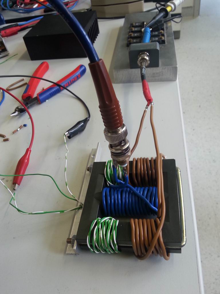
...i can confirm that the circuit from my hand drawing is working. I've
just built up such a transformer, see attachment. The test was done on
475 kHz, into a dummy load.
Now the power into the dummy load drops when saturating the outher
legs. And the supply current of the PA drops too. And the voltage still
looks like a sine wave! :-) So this is the right way.
But the transformer does not pass all the power through the dummy load.
When connecting the dummy load directly to the PA, then the power is 6
times higher. So the stray inductances seem to be to high. Maybe this
can be improved by spreading the secondary winding more equally arround
the outher legs.
Also the power difference between saturated and unsaturated transformer
is just 4.5 dB when 5A DC is applied to 2x 20 turns. It will also help
to use more DC turns, more equally spaced. Will try that later...
73, Stefan
Am 19.04.2017 14:41, schrieb DK7FC:
Hi Markus,
Am 19.04.2017 12:41, schrieb Markus Vester:
Hi
Stefan,
I think you'd have to do it the other way round, i.e. place the
saturable reactor in series with the load.
Without DC, the reactor will present high impedance, minimizing RF and
supply current. You could use a small parallel C to tune out the large
inductance.
Yes, right, that is what Andy means with tank circuit i what i mean
with series resonance circuit :-)
But see that image:
https://de.wikipedia.org/wiki/Datei:Kernanordnung_Transdunktor.jpg
How
should it work? I tried that circuit too, the results are similar, as
expected.
What about the circuit from my attachment? The windings labeled with DC
and switched anti-series, so that the AC voltage componsates. The AC
output winding is switched in series, so that the voltage doubles. When
the two other legs are saturated there is still a magnetic conductive
leg in the center, like a rod. This could still provide enough L for
the primary coil. The DC H fields compensate in the center leg. Could
work, right?
A saturated leg acts as not present, not like short cut. Or we can see
it as a DC current steerable air gap :-)
I'll try that in the evening...
73, Stefan
|
 Resize of 20170419_161627.jpg
Description: JPEG image
|