Hi Markus,
Am 19.04.2017 12:41, schrieb Markus Vester:
Hi
Stefan,
I think you'd have to do it the other way round, i.e. place the
saturable reactor in series with the load.
Without DC, the reactor will present high impedance, minimizing RF and
supply current. You could use a small parallel C to tune out the large
inductance.
Yes, right, that is what Andy means with tank circuit i what i mean
with series resonance circuit :-)
But see that image:
https://de.wikipedia.org/wiki/Datei:Kernanordnung_Transdunktor.jpg How
should it work? I tried that circuit too, the results are similar, as
expected.
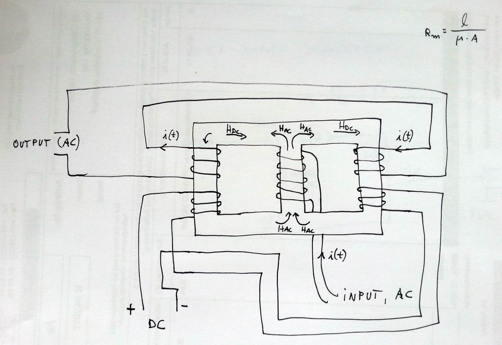
What about the circuit from my attachment? The windings labeled with DC
and switched anti-series, so that the AC voltage componsates. The AC
output winding is switched in series, so that the voltage doubles. When
the two other legs are saturated there is still a magnetic conductive
leg in the center, like a rod. This could still provide enough L for
the primary coil. The DC H fields compensate in the center leg. Could
work, right?
A saturated leg acts as not present, not like short cut. Or we can see
it as a DC current steerable air gap :-)
I'll try that in the evening...
73, Stefan
|
 Resize of 20170419_143458.jpg
Description: JPEG image
|