Dear George, LF Group,
I have attached the 9kHz loop/preamp/filter schematic again, as it would
seem some explanation would be useful - OK, here goes...;-)
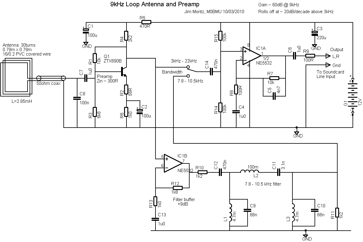
There are basically 3 frequency response determining elements in the design.
The first is the loop inductance, the shunt input capacitance C8, and the
input resistance of the preamp (about 300R, determined mostly by resistors
R1, R2 and R4, which also set the gain of the input stage). These together
form a singly-terminated, second-order low pass filter with a roughly
Butterworth response and cut-off frequency something over 20kHz. The preamp
stage gives about 30dB gain, and a reasonably low noise level - evidently
below the external band noise. This was arrived at after some
back-of-envelope calculations and tests of likely noise levels, induced EMF
in the loop, and so on.
The second element is the op-amp gain stage IC1A. This is configured as a
"lossy integrator", with a gain that rolls off at 20dB/decade in the
operating frequency range. This compensates for the loop output, which rises
at 20dB/decade below its cut off frequency, due to the loop EMF being
proportional to d(phi)/dt. It isn't essential to do this, but I felt this
would be useful in comparing noise levels, etc., and reduce the likelihood
of overloading by VLF utilities. At 9kHz, the gain of this stage is about
30dB also; the overall 60dB gain gave a good signal level for the audio line
input socket on my lap-top, determined by trial and error.
The final element is the bandpass filter. This was a straightforward ladder
filter designed with a n=3 Butterworth response, with the component values
fiddled a bit to suit off-the-shelf inductors. I aimed for an impedance
level that could easily be driven by normal op-amps. The filter is
terminated by 1200ohm resistors R10, R11, which are necessary to give the
correct response (actually, the initial design values were about 900ohm or
something, but I increased the value to "absorb" the loss resistance of the
rather low-Q 4.7mH inductors). The IC1A stage has a high input impedance
that does not load the filter significantly, but the input preamp stage has
a fairly high output impedance, and its gain would also be affected by
connecting the filter as a load. So the IC1B buffer stage was included,
which also provides 9dB gain to make up for the 6dB loss between the
terminations, plus approximately 3dB insertion loss of the filter.
So all the parts of this circuit were designed to work together - if you
wish to build a circuit with a different antenna, or use the filter in a
different system, you need to take similar considerations into account -
there are a near-infinite number of feasible solutions that will perform as
well or better, but all will have differences.
Cheers, Jim Moritz
73 de M0BMU
 9khz_loop_preamp_v2.png
Description: PNG image
|