Hello Paul, here's a link to my prototype build, the more I think back
to bad drain waveforms the more convinced I am that the major fix was
added decoupling. I read Jay's very salient post about none inductive
probing, but for clarity my scope captures are with two X10 probes
with the hooked spring tips on, and the normal ground leads both
clipped to the driver board PCB ground plane, next to one another, so
nothing careful done there to get those captures.
As we seem to be running short of ideas re the amp itself, bar
decoupling and short gate wires, what about the LPF?? I used blue
polypropylene (I think...) caps of about 1500V DC> Each section is in
its own totally sealed box, the mid toroid has two windows milled in
the box with gauze over them for a PC processor fan to blow air across
the inductor. Each outer box feeds through to the mid one via drilled
holes of about 10mm diameter with the inductor wires in Teflon
sleeving. Directly soldered. Caps are in each end box.
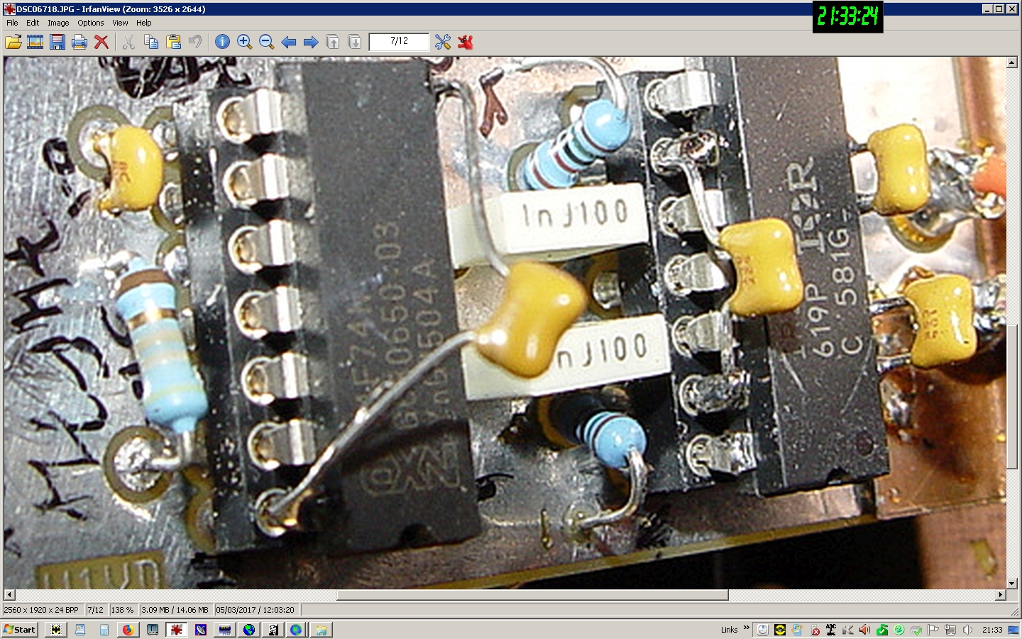
Decoupling caps are at http://www.chriswilson.tv/decoupling.jpg
they are done on the actual board of the MKII amp ;) But functionally
there was no difference.
Tuesday, April 10, 2018, 9:04:45 PM, you wrote:
> OK, let's switch topics a bit.
> I have a serious drain circuit ringing problem that most builders
> apparently don't have. Many things change all but the first peak of
> the ringing, but that first one is stubborn. It almost seems like
> that first big peak is being "forced" to occur somehow.
> I believe someone mentioned, though I cannot find it now, that cross
> conduction (one phase starting to switch on before the other is
> completely off) would exaggerate ringing.
> I've become curious as to whether the timing in my amp is correct.
> No one has really commented on this aspect. My driver board is
> unique and it would not be at all surprising it it has stray
> capacitance in excess of most!
> Here are the two gate waveforms overlaid so you can see the crossing:
> http://www.n1bug.com/gates4-wdv13.jpg
> And here are the drains similarly overlaid to show the crossing:
> http://www.n1bug.com/drains2-wdv13.jpg
> *Is* this OK or could the timing be just a bit off? I lack the
> knowledge to interpret what I am looking at.
> *If* it could possibly stand some improvement, do I have control
> over it? I think the 1000pf caps and 15k resistors on the IR2110
> inputs would affect this timing but I haven't been able to work out
> exactly how or what to change if I wanted to experiment:
> http://w1vd.com/137-500-KWRev3.0.pdf
> Paul
--
Best regards,
Chris mailto:[email protected]
|