Hi Mal,
The whole point of this design is that the output impedance is 50 ohm,
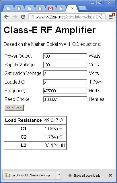
therefore there is no need for impedance transformation! Try
calculating the values for a 100 V, 100 W Class-E transmitter and note
the output impedance. I used VK2ZAY's online calculator (see attached)
plus my own class-e calculator and derived exactly the same values. I
don't know how you derived the 7 ohm value.
I am also looking at the scope shot after the low pass filter, it
looks pretty close to a sine wave to me. That is the last picture on
the page, which has the gate voltage on trace 1 and the output voltage
on trace 2. I don't see any spikes. I will agree that the gate voltage
has a bit or ringing which could be bad, I will need to add a ferrite
bead on the gate leg of the FET and a low value resistor in series to
reduce its amplitude.
Finally, I agree that using an air core inductor may be slightly more
efficient, but I am just happy with the achieved 90% efficiency and
using the T200-2 toroid makes the whole thing more compact.
73, Dimitris VK1SV
2013/2/6 mal hamilton <[email protected]>:
> Dimitris
> I do not understand how you have arrived at a 50ohm load output without a
> matching transformer after the Tank circuit. The Fet Impedence is around 7
> ohms and needs to be transformed to 50 ohms via a transformer, then a LPF is
> necessary.
> Have I missed something. Also your trailing waveform has a voltage spike
> which means it is not switching at the correct time.
> I have built this type of amplifier for 500 Kcs and found it worked as
> specified after setting it up for spot on switching as instructed by the
> designer.
> g3kev
>
>
>
> ----- Original Message -----
> From: "Dimitrios Tsifakis" <[email protected]>
> To: <[email protected]>
> Sent: Tuesday, February 05, 2013 12:50 AM
> Subject: LF: My transmit converter description
>
>
>> Hello group,
>>
>> My transmit converter is now finished and tested - it survived two
>> sessions of 50% duty cycle WSPR transmissions on 475 kHz and the
>> results are great. I thought others may find this useful, so I have
>> put a write-up on my web page:
>>
>> http://people.physics.anu.edu.au/~dxt103/472/nltt/
>>
>> It is a 50 W class-e PA designed for 50 ohm impedance, so there is no
>> need for an impedance transformer. Doesn't get simpler than that :-)
>> The driving circuit is based on G3XBM Roger's design with the
>> difference of a 10 MHz OCXO LO and the addition of a beefy MOSFET
>> driver.
>>
>> 73, Dimitris VK1SV
>>
>
>
 class-e_50ohm_out.jpg
Description: JPEG image
|