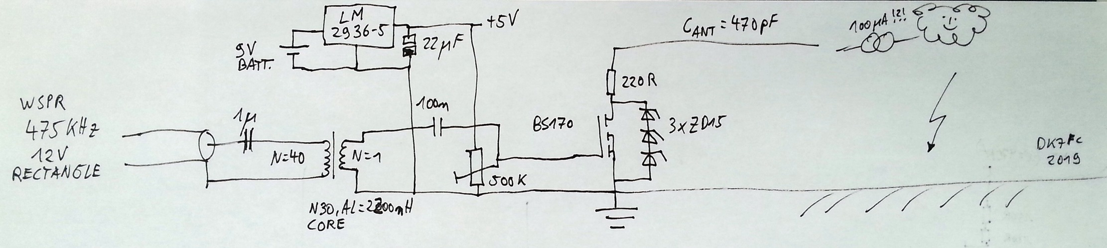
...the circuit is completed (attached).
First i used a simple rectangular input signal coming from the source,
over an ferrite core. The gate voltage was +-10V. But then, obviously
due to the FETs internal reverse transfer capacitance i got a 200 mVpp
output across 470 pF (tested in the lab, later to be replaced by the
antenna). I built a test source for the assumed 100 uA 'sky-current' by
using a 1 kV voltage source and 10 MOhm in series. As assumed, a linear
rising voltage was observed during the off-times of the FET. However,
together with the voltage coming over the Crss, the residual rms value
even dropped! Thus i had to reduce the gate peak-peak voltage and ended
up with the circuit shown in the attachment. There is a DC offset and
the AC component is as low as possible. The reduced the unwanted voltage
8 mV.
Then, 50 mV rms at 475 kHz at 100 uA DC 'sky-current'.
How far will a 50 mV rms WSPR signal be detectable? And will the
'sky-current' reach 100 uA at all? At least the signal strength will
rise with the square of that current, so the report are nearly as good
as a current measurement.
73, Stefan


Am 11.03.2019 13:29, schrieb DK7FC:
Hello Jim,

Yes, indeed.
I'm now preparing the circuit and want to set it up in the evening.
Found an IRF820 in the 'junk box', a good choice. Or, maybe even a
BS170 will work. It handles 60V only but i had the following thought:
The ERP at a constant voltage across the antenna (say 50 V rms at the
fundamental frequency) will rise with the sqare of the frequency (for
electrically short antennas). But that voltage will not be constant in
practice. It will drop linearly with the frequency ( ~ 1/f) because
the sky-current is assumed to be constant and the charge up time is
T/2. And, doubling the voltage at the antenna will also rise the ERP
by a factor of 4. All in all it means the the ERP is constant, or
independend of the frequency!?
That means, it would be wise to select a band where many RX stations
are watching and propagation is promising. The number of RX stations
is higher at MF but (groundwave) propagation is better at LF.
Since the peak voltage will be lower at MF (shorter charge-up time),
MF is less critical.
And which mode?! I think the best choice is a 100% duty cycle WSPR
beacon. It also has the advantage that one can check the results in
the database. And there are many RX stations, even in the groundwave
distance and even in less than 100 km here. And i have my tree which
can detect small differences at very low levels.
At MF, the BS170 is a good choice i think. And it can be driven by a
Raspi directly, maybe with a ferrite transformer in the gate-source
path, to decouple the shack from the antenna...
If that works, one could try LF.

73, Stefan


Am 10.03.2019 20:18, schrieb [email protected]:
All great ideas in the preceding messages.
A steady signal from the 136 kHz sky-current transmitter could
indicate that a data bit might be available later from the 10 Hz
sky-current transmitter.
Agreed, the triggered gap sounds better than an HV vacuum relay (for
jitter and reliability).
Sounds like the voltage divider doesn't need to be more than a
gigohm, but perhaps for future reference: a reliable 50kV 1 terohm
divider can be made very easily: encapsulate ten 100 gigohm resistors
in hard epoxy, being sure not to touch them during assembly. A single
linearity calibration after curing will be remain valid +/- 10% for
years in varying humidity and temperature.
73,

Jim AA5BW


-----Original Message-----
From: [email protected]
[mailto:[email protected]] On Behalf Of DK7FC
Sent: Sunday, March 10, 2019 5:52 AM
To: [email protected]
Subject: Re: LF: Re: Re Loomis?&  ... 12.47 Hz

Hi Jacek, DC,

Yes yes, i already see a new project for summer :-)
A floating antenna will charge up to a voltage where the E field
strength is high enough to start partial discharges, something like
20 kV maybe, depending on the wire diameters and homogenity of the
arrangement, also on pressure and humidity. So there will be a
voltage limit given by the arrangement. But a higher field strength
in summer will help to charge up the antenna faster, so higher
switching frequencies are possible.
One could build/use a triggered spark gap,
https://en.wikipedia.org/wiki/Trigatron, this will hold higher
voltages and you can connect the trigger directly to a ublox GPS
module running e.g. at 3 Hz :-) I think this will give a lower jitter
than when using a vacuum relay.
Could this work over my 3.5 km path if i use my inv-L? I don't think so.
The time to integrate will be to short and there will be much QRN
during such an experiment, so the SNR will be very low. Currently (at
12.47 Hz) i already have 15 kV DC available...
Anyway, interesting questions, there is something interesting to learn.
Maybe i will do a few experiments in summer. Building a HV divider
and measurement should be no problem...
73, Stefan
PS: Assuming 100 uA constant current 'coming from the sky', my 470 pF
antenna would charge up with 213 kV/s, so it would be possible to
switch at 10 Hz and get a 21 kV 'square wave'. Maybe the harmonics
could be detected easier than the fundamental frequency.
At 137 kHz it would be 1.5 V only (0.53 V rms). This can be switched
with a normal FET! Imagine we would switch the antenna permanently
at, say 136.172 kHz, using a FET and a ublox GPS module. Then, as
soon as the field strength is high enough, we would see a carrier on
the grabbers? We need to try that out! Amazing! What a great hobby we
have!?!
PPS: For this experiment, the antenna can be series resonated, which
would help to concentrate the energy to the wanted spectrum...
Am 10.03.2019 09:58, schrieb Jacek Lipkowski:
I haven't tried this with 300m kites, but even ordinary low-band
dipoles can charge quite quickly if they are high enough, so 100uA
seems to be a good approximation. This is already comparable with the
170uA you're getting at 12.71Hz now (and which will be lower at lower
frequencies).

The only problem is the switch, but a high voltage vacuum relay (or a
few in series with a piece of fiberoptic for controlling each of them)
should be sufficient upto a few Hz.

Also note that the more charge in the atmosphere, the more ERP you
get. But it also gets more dangerous. No risk no fun on the "loomis
band" :)

VY 73

Jacek / SQ5BPF


On Sat, 9 Mar 2019, DK7FC wrote:
Date: Sat, 09 Mar 2019 22:31:41 +0100
From: DK7FC<[email protected]>
Reply-To: [email protected]
To: "[email protected]"<[email protected]>
Subject: LF: Re: Re Loomis?&  ... 12.47 Hz

Hi Jim,

I hope you don't mind that i'd like to share the email with the
reflector, because i've a thought that might be interesting.

In my view, the Loomis experiment it is rather the detection of a
changing current (charge per time) on the RX site. The changing
current is coming from a change in the static electric field, caused
by the shortcutted 'TX' antenna. Something like a current divider.

In 2010/2011 i've done VLF transmissions on my own, using a 300m
vertical kite antenna (having a special licence for that altitude).
The antenna capacity was about 1.5 nF. During an experiment in the
summer time there was a short moment when the vertical wire was
floating. It quickly charged up to some kV, which was quite noticable
when i catched and touched the wire then!! Since that time i
carefully kept the wire grounded during such experiments.
So, it means that the wire charged up, so there must be some
continuous charge flowing onto the wire and, if the wire would be
grounded permanently, you could probably measure a more or less
stable current, i guess it would be some 100 uA.
Now imagine someone else would rise a grounded kite in a few meters
distance. This would certainly affect the current flowing in my kite
wire.
The farer both 'antennas', the lower expressed the effect will be and
the higher the antennas, the stronger it will be expressed.

I think the effect would be much better expressed by measuring the
voltage across a 1 MOhm resistor instead, which could be done by
using a scope and some overvoltage protection!
Actually an interesting question: In the summer time, which DC
voltage could be measured over a 1 MOhm resistor when connecting to a
large E field antenna and ground?
And, a next step: If i let my antenna charge up (floating) and then
discharge it in exact time intervals, say each second, then i should
see something at 1 Hz on a suitable receiver. This would already come
close to the experiment i'v done. I'm just replacing the 'natural
charge source' by a high voltage power supply and modulate that
voltage (with a sine wave, not rectangular).

So, to answer your question, i think that Loomis experiment was not
dedicated ELF, it was rather a broad-band spectrum that was radiated,
since the charged antenna was discharged immediately. For a real ELF
transmission i would say that the carrier frequency has to be at ELF,
not the modulating frequency. OK here you might say the carrier
frequency is
0 and it is AM modulated...

Try to repeat the experiment! Use smaller antennas and shorter
distances. Could be interesting :-) Rise two 10m high wires in 10m
distance in an open field. Connect one of them to a scope (1 MOhm
input resistance), protect the input with a glow lamp. Keep the other
wire floating.
Select 1 second/div. If there is a thunderstorm coming and you can
see a rising DC level on the scope, then do a shortcircuit on the
other wire. I bet you will see the voltage dropping on the scope.

73, Stefan


Am 09.03.2019 19:10, schrieb James Hollander:
       Hi Jacek and Stefan,     I?d like to suggest that while I can?t
say for sure there weren't ELF frequencies received in the Loomis
       experiment of 1866, I?m hesitant to reach the conclusion ELF
was used by Loomis because of the following questions.
       1) If the transient current that flowed when Loomis?
transmitter circuit was closed probably lasted only a few
milliseconds, wouldn?t the modulation frequency content exceed at
least the upper ELF boundary 30Hz as impressed on the ?carrier??
       2)  With a 600? long TX antenna and only a galvanometer fed by
similar height RX antenna, wouldn?t any radio waves that might have
been received be shorter than 10x the wavelength for which a 600? TX
antenna is a quarter wavelength?    10x(600?x4)=24000? or about
8km.   If the
wavelength is less than about 8km, wouldn?t the ?carrier? frequency
content exceed about  37 KHz?
       3)  Nevertheless, one might say, if galvanometer deflected
temporarily in Loomis? system, it must have detected some near-DC
content
unless some nonlinear element were in the receiving circuit.   If I
Fourier Transform a damped DC transient, what is the frequency
content?
       4) If there were DC transfer, wouldn't we say it's in the
nature of a current charging an atmosphere-ground capacitance through
the ground resistance, not radio in near field ELF?  Or should we say
the meaning of ?frequency? in this case becomes so fuzzy that Loomis
both did and didn?t use ELF?
       5)  If indeed Loomis communicated any ELF, can?t one still
radically distinguish the 12.67 Hz experiment at DK7FC as involving a
very narrow band  continuous wave with 227 hours integration of this
continuous wave to detect it and make it separable from other waves
that could be generated in the ELF band?
       I?m new to the subject of ELF, and would appreciate any words
of wisdom you?d like to give.
Vy 73, Jim Hollander W5EST


-----Original Message-----
From: Jacek Lipkowski<[email protected]>
To: rsgb_lf_group<[email protected]>
Sent: Sat, Mar 9, 2019 4:28 am
Subject: Re: LF: RE: RE: Almost touching the ground... | 12.47 Hz

Actually a similar experiment to Stefan's has been done already, and
at much lower frequencies (almost 0Hz :):

http://aerohistory.org/Wireless/loomis.html

In this case the power supply is from the cloud electric field and
probably had quite a few more kV than Stefan's.

Please note the DX distance.

VY 73

Jacek / SQ5BPF

From: DK7FC<[email protected]>      To: rsgb_lf_group
<[email protected]>
Sent: Tue, Mar 5, 2019 12:50 pm    Subject: ELF: Almost touching the
ground... | 12.47 Hz
Hi ELF friends,        During the last 2 weeks i've done another
experiment on ELF, this time
on 12.47 Hz, the 24 Mm band (wavelength 24057 km). Again i've crossed
the local distance of 3.5 km. That's the lowest frequency i've ever
been and it feels like i can see the ground already :-)    The
dimensions of everything down there are extreme. I've integrated 227
hours of a carrier transmission into one spectrum peak, it is shown
in the attachment in 1.25 uHz. This carrier could have transferred an
EbNaut message of nearly 100 characters.

The ERP was 50 attowatt or -163 dBW and the antenna current was 170
uA only, despite about 5 kV antenna voltage.

I'm now trying to put a step below 10 Hz but the RX antenna becomes
less efficient with each Hz. 73, Stefan
 Loomis transmitter test circuit.jpg
Description: JPEG image
|