Return to KLUBNL.PL main page
| To: | [email protected] |
|---|---|
| Subject: | Re: LF: A transductor instead of a traditional variometer on VLF/LF/MF? Done! |
| From: | DK7FC <[email protected]> |
| Date: | Mon, 16 May 2016 23:13:15 +0200 |
| In-reply-to: | <[email protected]> |
| References: | <[email protected]> <[email protected]> <CAMFjj71q9jJDHLvgtYJJ4EqK9=9w8zoLTucq6i6BgnP1i4ruUw@mail.gmail.com> <[email protected]> <CAMFjj70zAo+NvzX4ZTj_DbiL2rx6NNq-ZzrVAnHiT1Mar9APPQ@mail.gmail.com> <[email protected]> <[email protected]> <[email protected]> <[email protected]> <[email protected]> <[email protected]> |
| Reply-to: | [email protected] |
| Sender: | [email protected] |
| User-agent: | Mozilla/5.0 (Windows; U; Windows NT 6.1; de; rv:1.9.1.8) Gecko/20100227 Thunderbird/3.0.3 |
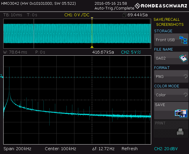
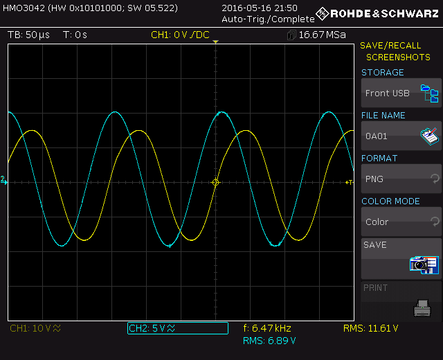
Hi all,Now i have done more tests and took some oscilloscope screenshots. The transductor is now part of the VLF system. It is not placed in the cold end any more but 'above' the output transformer and 'above' the antenna current measurement. I have checked the range of frequency variation at 250 mA antenna current. It reaches from 6470 Hz (I = 0) to 6500 Hz (I = 250 mA). So the needed DC current is quite low. With 2A DC it may be possible to go up to 6505 Hz but that is not worth the 'effort'. I just took a 12V battery and a 50 Ohm resistor. By switching forth and back i saw the difference of the antenna current was 250 mA to 220 mA, i.e. 1.1 dB. 1.1 dB can decide between a decode and nothing, we know. Anyway the variation range could be higher. Maybe i will build a version with 12 cores or so, later, on 5170 Hz. Two screenshots are attached. They show the spectrum and sine curves (and their distortion or harmonics) when the transductor is effective, i.e. I = 0. One shows a spectrum of the E field, ratiated from the wire. Harmonics seem to be almost 60 dB down. The other one shows the Drain-Ground voltage (= Drain-Source + 0.1 Ohm) of one of the PA FETs (yellow) and the voltage measured by the probe when capacitively coupled to the radiating antenna (blue). It all looks very fine.Ah and i run a 260 mA carrier for about 30 minutes and touched the transductor after that. It was almost cold, maybe 10 K above ambient temperature... 73, Stefan
|
| Previous by Date: | Re: VLF: EbNaut transmissions on lower frequencies?, pre-tests: 6.47kHz, DK7FC |
|---|---|
| Next by Date: | LF: TS 590, Mal Hamilton |
| Previous by Thread: | Re: LF: A transductor instead of a traditional variometer on VLF/LF/MF? Done!, DK7FC |
| Next by Thread: | Re: LF: A transductor instead of a traditional variometer on VLF/LF/MF? Done!, Rik Strobbe |
| Indexes: | [Date] [Thread] [Top] [All Lists] |