Hi all,
I have built such a transductor today. It is intended for VLF resonance
adjustment but it will work on LF and MF and HF too, i bet.
Can someone of the LF and MF TX stations try that please? I think it is
the most comfortable way to realise a steerable 'variometer' without
mechanical components.
Now, i took 4 of my 100 cores of the 3C85 ferrite. Each one has an Al of
4 uH.
First i wound an AC winding with 22 turns:
https://dl.dropboxusercontent.com/u/19882028/VLF/Transductor%20AC%20winding.jpg
At 5170 Hz and 0.3A, this is the number of turns to prevent the core
from saturation. For the AC winding, the cores are in series, so the Al
= 16 uH. With 22 turns and Al = 16 uH, L = 7.74 mH.
Then i added a winding for DC. For saturating the cores with a DC field,
I * N is constant, so i took a thin wire and many turns because it is
easier to generate 0.5A at 5V then 10A at 0.25V :-)
For the DC winding, N = 20. There is still room for another 20 turns but
this is a first test. The DC winding must be wound anti-serial! Actually
it is a ferrite transformer and you will short cut the transformed AC
voltage that appears on the DC winding. So you need to wind two windings
on a half of the construction and switch them anti-serial, so the AC
voltage is compensated but the cores can still be saturated by the DC
current.
https://dl.dropboxusercontent.com/u/19882028/VLF/Transductor%20ACDC%20winding.jpg
While winding the DC winding, you need to listen to ACDC, whether you
want to or not!
For a test, i build a resonance circuit (
https://dl.dropboxusercontent.com/u/19882028/VLF/Transductor%20test%20arrangement.jpg
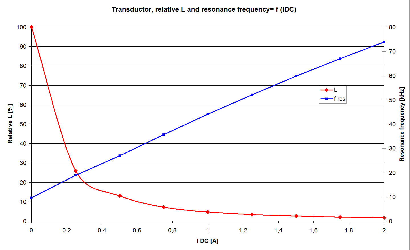
) and measured the resonance frequency as a function of the DC current:
C= 33 nF

I [A]    |    f res [kHz]       |    L [uH]    | relative L [%]
-------------------------------------------------------
0        |    9.59                |    8346        |    100
0.25   |    18.88              |    2153        |     26
0.5     |    27.03              |    1050        |     13
0.75   |    35.66              |    604          |    7.2
1.0     |    44.1                |    395          |    4.7
1.25   |    52.03              |    284          |    3.4
1.5     |    59.8                |    215          |    2.6
1.75   |    67.0                |    171          |    2.0
2.0     |    73.9                |    141          |    1.7
BTW, in all measurement points, the wave form looked like a perfect sine
wave!
A graph is attached. Look at the linearity of the resonance frequency.
The only thing that is can't understand: If this is a known circuit, why
does no one of use it for LF and MF for an easy resonance tuning??????
This circuit in series with a fixed coil can give a variable resonance
just in the desired range, e.g. 135.7...137.8 kHz!
I will now double the number of turns for the DC winding and insert that
construction into my VLF system. I will let you know in which range i
can vary the resonance frequency. Most likely i will need 3 of these
circuits in series.
73, Stefan


Am 14.05.2016 21:16, schrieb Warren Ziegler:
Hi Chris,
      Yes some serious mechanical engineering involved!
My good friend Marshall designs vlf antennas for the military and has
worked on NAA.
In fact Marshall worked with Dr. Wundt, the fellow who built the
Goliath vlf antenna in Germany in WWII and was later brought to the
U.S. in Operation Paperclip. Wundt did the original design for NAA.

Great stories!

73 Warren

On Sat, May 14, 2016 at 12:16 PM, Chris Wilson<[email protected]>  wrote:
Hello Warren,

Saturday, May 14, 2016

Fascinating stuff, thanks for posting that, shame there are no photos,
do you know where one might see some photographs of these giants?


Best regards,
  Chris  2E0ILY                          mailto:[email protected]
Yes NAA uses a saturated core reactor:
http://coldwar-c4i.net/VLF/design.html
 transductor graph.png
Description: PNG image
|