|
>> the
humiliation of being a significant part of a mHz off QRG,
;-) The
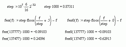
upside is that such offsets are perfectly deterministic. Knowing your
clocking scheme, and assuming that your controller always rounds to the
next-lower frequency word, we find that 137477 is low at -629 uHz
low, and 137777 only -91 uHz, apparently
matching observations. If you had chosen nearest integer
rounding, 137477 would have been somewhat closer at +244 uHz ;-)
In the context of using PSK / Wolf modes with
nonlinear amplifiers, DL4YHF had long ago included a continuous phase ramp
option in SpecLab's digimode modulator. My conceptual problem is that I never
know which way to swing around - at each transition one has to make
an arbitrary decision between a low or high frequency
spike...
All the best,
Markus (DF6NM)
Sent: Saturday, November 14, 2015 9:47 PM
Subject: Re: LF: Ramped BPSK
Hi Andy,
I was about to solder a dpdt relay across a
transformer until I saw your
posting. The DDS here is the 9851 and the
40 bits are loaded serially.
If bits 35-39 are changed from 00000 to 00010
the phase will change by
180 degrees and so the soldering iron can be
switched off?
An AD9852 would spare me the humiliation of being a
significant
part of a mHz off QRG, but these chips seem hard to get.
Markus was
right about the resolution. The DDS is clocked at 10 MHz with
the
x6 multiplier. The output is then divided by 16. The resolution is
just
under 1 mHz and so the frequency error depends on the output
frequency.
73 Joe VO1NA
On Sat, 14 Nov 2015, Andy Talbot
wrote:
> Try the Anlaog Devices web site - www.analog.com
>
> I built my own
PCB, http://www.g4jnt.com/AD9852module.pdf
(PCBs are no
> longer available for that, though). That particular
DDS is a bit out of
> date now. I use it for this job as I
have a few modules left, and it is
> one of the few devices with
both a 48 bit frequency setting register and
> amplitude
programmability.
>
> Andy G4JNT
>
> On 14 November
2015 at 19:20, Paul Nicholson <[email protected]>
wrote:
>
>>
>> With sufficiently brief phase steps,
those discrete sidebands
>> will fall outside the loading coil
bandwidth and be well
>> attenuated.
>>
>> But, does
that bring back the audible clicks from the PA
>> and
coil?
>>
>> I'm keen to have a play with these DDS
chips. Is there a
>> recommended evaluation
board?
>>
>> --
>> Paul Nicholson
>>
--
>>
>>
>
|