Dear Paul, LF Group,
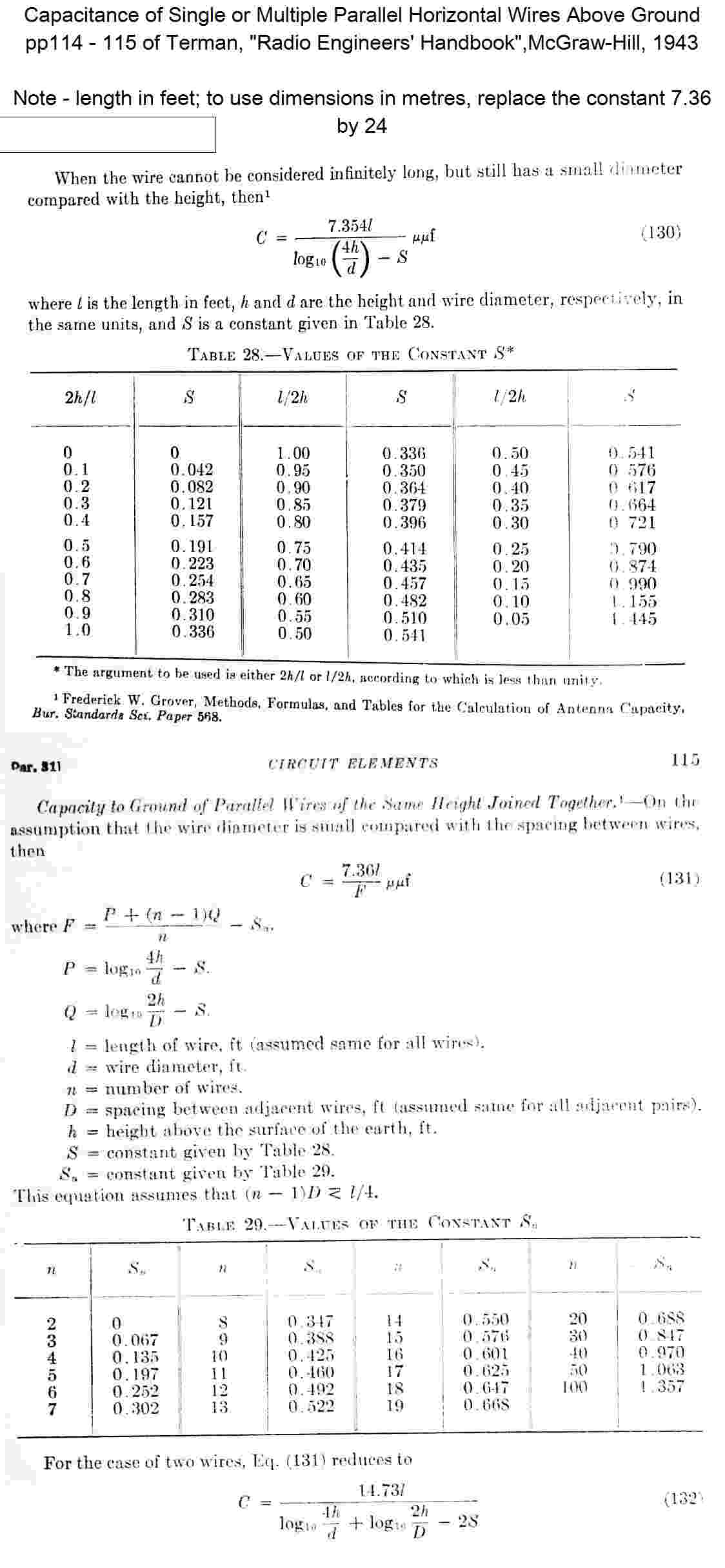
I have attached an excerpt from Terman's "Radio Engineers' Handbook", which
gives formulas and tables for calculating capacitance of multiple parallel
wires.
A more general way of calculating capacitance of antennas is to use one of
the NEC-based antenna simulators. Doing an "SWR" simulation using "perfect"
ground and lossless wires gives you an impedance consisting essentially of
the capacitive reactance plus the radiation resistance. I have found this
gives results that are reasonably close to reality, and can be used for any
complicated collection of wires. Also it gives you a way of optimising the
radiation resistance.
As far as Paul's antenna goes, obviously what is possible will depend on the
location of the mast and its surroundings, other antennas, and so on. A
straightforward way of increasing C would be to connect additional sloping
top-loading wires at the insulator at the top of the tower, and fan them out
over as wide an angle around the tower as possible, to maximise spacing and
so capacitance. Having the top loading wires coming close to ground level
would be detrimental for radiation resistance, so it would be better to make
the added wires shorter than the existing wire, or better still if possible,
support the ends higher off the ground. Remember that basically you want to
have the greatest possible average height of the wires to maximise Rrad, as
well as a long wires to maximise C, so a trade-off is likely to occur.
In my "tree current" experiments, I found that roughly twice as much current
flows to ground through the tree trunks at 136k as does at 500k, for a given
antenna and antenna current. This is consistent qualitatively with the
reduction in Heff, and increase in Rloss that occurs at the lower frequency.
This would suggest that trees would have an even greater effect at lower
frequencies like 9kHz, although there is probably a lower cut-off frequency
below which the current distribution is determined entirely by the
proportion of total antenna capacity between the trees and the actual
ground, and the resistance of the trees is much lower than the capacitive
reactance of the tree path.
Cheers, Jim Moritz
73 de M0BMU
 pp114_115.jpg
Description: JPEG image
|