Return to KLUBNL.PL main page
| To: | [email protected] |
|---|---|
| Subject: | Re: VLF: Earth antenna transmissions on a guide rail?!?? 2nd day... |
| From: | DK7FC <[email protected]> |
| Date: | Mon, 30 Jul 2018 21:31:23 +0200 |
| Dkim-signature: | v=1; a=rsa-sha256; c=relaxed/simple; d=posteo.de; s=2017; t=1532979086; bh=H+rsrwZWlVhe1FPnnUwNISgcFEFEzTOcuh9vTyHKK6U=; h=Date:From:To:Subject:From; b=UAsYfOSiDthONOpKG00k8ErpZDwWny+6Sk2K8V8aju9wCrroZ77qBsy9/ptitRUif YkC69RaBn07CEkV08CNRJ6Igh8hm/mgd/IEnQnxPgxBVuXKHAR9e8W75tAq0/kJQRr vOTRhVloJ4Kf0ML/c9PZb0eDO+muV5+bsOtJohY1HIxqGGGQHsluYAhvRPj0YIhrGz mBVD0yeSNADG9m3Dth+hCN/RURti5WYPhNqSXlVKUTyhGKh+vz1zEu01Z7G8x8kxLj W9/7yxGxxlJYMLnkGpaT1//h8Mm0+mjoFQr/22q0tDSGypFRqCqcYPPQpJH5WcO6lq 5gYf2tpi7a6LQ== |
| In-reply-to: | <[email protected]> |
| References: | <CA+GfORvAA10STf3zWSQ-dRFwk5BBS25Ht0x8cDZ3cYTa09dYbw@mail.gmail.com> <[email protected]> <[email protected]> <[email protected]> <[email protected]> <[email protected]> <[email protected]> <[email protected]> <[email protected]> <[email protected]> <[email protected]> |
| Reply-to: | [email protected] |
| Sender: | [email protected] |
| User-agent: | Mozilla/5.0 (Windows; U; Windows NT 6.1; de; rv:1.9.1.8) Gecko/20100227 Thunderbird/3.0.3 |
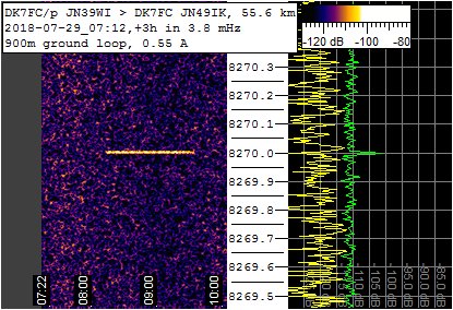
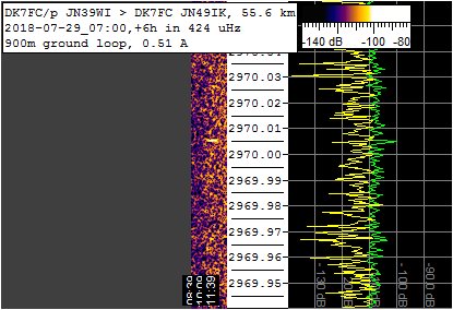
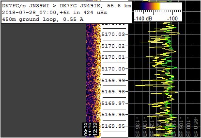
Hi VLF and ULF friends,In the attachment you can find 3 spectrograms from transmission of the last weekend. For the 8270 Hz and 2970 Hz transmission i took the data of the 900m ground loop, 5170 Hz is from the 450m ground loop. The 8270 Hz signal was very strong even in 3.8 mHz ('DFCW-600'). Some real QRSS-60 would have been possible! The spectrograms also show that there was no trace on the frequency of interest before and after the transmission (no traces from the right channel ( 1 PPS) ). A few minutes ago i built the switchable network for resonating the antenna properly. And i actually ordered 1000 m of that 0.75 mm^2 loudspeaker cable. Thus, in the next experiment i think the Q of the antenna will be much higher and it will be possible to tune it accurately. Then, the tuning capacitance will tell us what the ground loop inductance is! And then, we can calculate the depth where the current is flowing backwards in the ground, asuming a simple model in first steps. Next, we can see whether the inductance or depth stays constant at lower frequencies (hopefully it will increase!) by resonating the antenna at 2.97 kHz for example. BTW i measured the DC resistance of the wire i used last weekend, it is 116 Ohm, so it agrees well with the calculated 120 Ohm... The new wire should have 21.4 Ohm only.The big advantage of this antenna is that no high voltage and large coils are needed. Usually the voltage is the limiting factor for a VLF or ULF TX antenna. But not here. Here it is the power of the PA. The antenna could easily handle 2 kW, which means 5.16 A, no problem for the wire. And it would be a 20 dB stronger signal than last weekend... 73, Stefan Am 29.07.2018 23:11, schrieb DK7FC: As a next result from today's experiment, here is a spectrum peak of the 2970.005 Hz transmission. I reached 20 dB SNR in 180 uHz! This far more than expected, in July anyway. It is the first ULF transmission (by amateurs) from an earth electrode TX antenna, detected in the far field.Spectrograms will be produced soon... 73, Stefan Am 29.07.2018 16:01, schrieb DK7FC:Hello Roman, VLF, I transmitted pure carriers each time. It was just a first test.Today i've done a second experiment, this time using a 900m long wire! So the wire should have about 125 Ohm DC resistance. I measured 220 mA DC at 38.4 V, so the overall loss is 175 Ohm. Very interesting; the ground loss resistance stays at 50 Ohm although the distance between the electrodes has doubled! If i would use the 0.75 mm loudspeaker cable then i can reduce the losses by 100 Ohm which is more than 50 %, so i will gain 3 dB at the same output power! Then with a switch mode PA having nearly 100% efficiency i may gain 2 dB more (mmy lonear mode PA was not well matched today and quite warm). So maybe i can reach 1 A antenna current with just 75 watts??!!! Today i tuned to 550 mA antenna current again, at 8270 Hz. With the scope, i measured the phas, it was more inductive than yesterday. I actually found a 1 uF MKP-10 cap in my car and switched it in series to the antenna. This improved the phase slightly. Then i also found a low pass filter for 137 kHz, the pypical pi configuration, i.e. it acts as 4*22 nF in parallel here on this frequency. Switching this in series leads to a low current, so the C is to small. So for the next experiment i'm preraring a switchable C network (47n, 100n, 220n, 470n, 1u, 2.2u, 4.7u). It will be even more necessary when i lower the wire resistance (higher Q). Well, today the QRN was much lower, especially for the 2970.005 Hz transmission period. Yesterday this was totally buried in the noise on my RX on the tree. But today! I transmitted another 90 minutes with much lower QRN background. I already have a clear spectrum peak but i like to try to improve it a bit more before presenting it here.Todays carrier transmissions: 8270.000 Hz : 08:12...09:33 UTC 2970.005 Hz : 09:42...11:15 UTC Sorry for the confusing email ;-) 73, Stefan
|
| Previous by Date: | Re: LF: 2200m QSO Stations List, Alex R7NT |
|---|---|
| Next by Date: | Re: VLF: Earth antenna transmissions on a guide rail?!?? 2nd day..., Roger Lapthorn |
| Previous by Thread: | Re: VLF: Earth antenna transmissions on a guide rail?!?? 2nd day..., DK7FC |
| Next by Thread: | Re: VLF: Earth antenna transmissions on a guide rail?!?? 2nd day..., Roger Lapthorn |
| Indexes: | [Date] [Thread] [Top] [All Lists] |