Hi Tom, VLF
Thank you VERY MUCH for the detailed description of your Dream Tx for 36Km band
Different approach and neat construction. Congratulations !
J
Can you provide a part number for the Murata ferrite inductors?
73 de Luis
EA5DOM
Hello group,
having been QRV on LF since 1999 and on MF since 2013 now I try to dream on VLF too. First test results on 8270 Hz were quite encouraging - thanks to all reporting stations and to Paul Nicholson for the compilation! On 2018-01-28 13:00,+6h, Paul analysed my
signal in 46.3 uHz:
Bielefeld (DL4YHF 384.3 km): 15.7 dB, -27.6 dB/1Hz
http://abelian.org/vlf/tmp/180128a.gif
Cumiana (IK1QFK 601.4 km): 13.0 dB, -30.3 dB/1Hz
http://abelian.org/vlf/tmp/180128b.gif
Warsaw (SQ5BPF 710.2 km): 10.5 dB, -32.8 dB/1Hz
http://abelian.org/vlf/tmp/180128c.gif
Todmorden (Paul Nicholson 1071.3 km, ODX): 15.6 dB, -27.7 dB/1Hz
http://abelian.org/vlf/tmp/180128d.gif
Up to now I´m just testing the system with plain carriers from a synthesizer but later on there will be more sophisticated modes in use generated by a GPS controlled PC. Here is some information about my new VLF station and first experiences with its components
- hoping it won´t bother too much:
TX exciter: Frequency synthesizer Schomandl ND 60 M resp. MG 100 M, resolution 0.1 Hz. Although being controlled by an external rubidium standard, at audio frequencies precision and stability of both of these units are only in the 10 exp -8 range for some unknown
reasons. At LF, MF and HF they perform much better - so I don´t care for the future.
TX power amplifier: Commercial (low cost) stereo PA Omnitronic E-900 Mk 2, according to datasheet 2 x 300 W stereo output at 8 Ohms resp. 900 W in mono bridged mode. In spite of the distortions staying low one can´t use these maximum powers with long key-down
periods due to thermal overload. I already realized minor improvements by modifying the internal air flow. Bridged mode doesn´t work because of phase differences between the channels at least at 8,27 kHz (Markus, DF6NM, has reported on similar experiences
with another PA). So I only use one of the stereo channels, the available power being sufficient anyway.
TX antenna: The idea was to use the exsisting facilities as far as possible and to be able to reactivate all former modes (LF, MF, HF) in a simple way. So I stayed with my proven Marconi-T-antenna, 13 m up with a top load of 4 wires, 33 m long and seperated
1 m. At 8,27 kHz its mesured loss resistance is about 160 Ohms and its total capacity to ground about 660 pF, the latter in good accordance to Watt´s formulae. The loading coil is somewhat different of the usual concepts because I wanted a very versatile unit
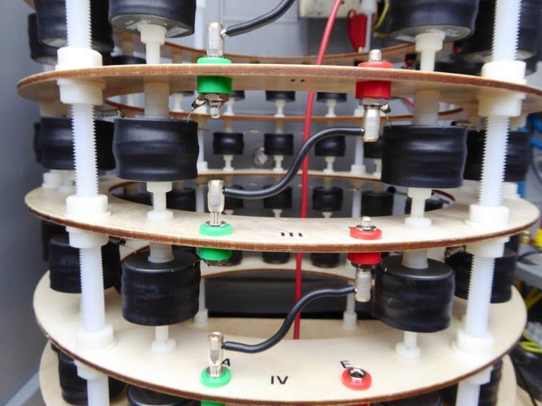
with low required space to fit into the antenna box at the back of my arbour. I came out with a construction of 60 ready bought ferrite inductors 10 mH / 600 mA rms (Murata) mounted on 4 ring-shaped layers of ply wood, 30 cm diameter and 30 cm height over
all. The variation range by tapping and the use of variable mutual coupling is 10 ... 700 mH . In a work bench resonance test the 700 mH coil easily withstood 20 kV rms without any partial discharge or overheating. Fine tuning is accomplished by an additional
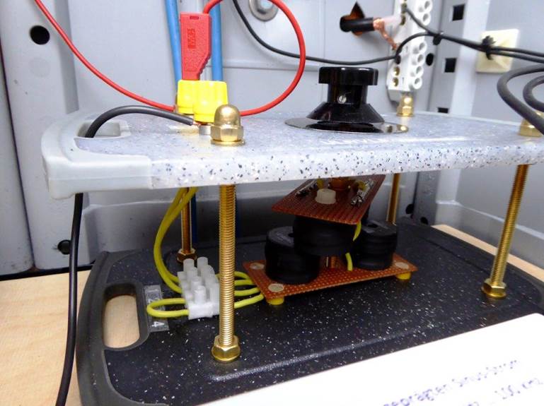
variometer 7 ... 14 mH made by two pairs of the same ferrite inductors, mechanically twistable against each other face to face. A rms current meter (1 A full scale) allows to tune the coil assmbly to resonance. When increasing the current the resultant inductance
of the coil also increases a little bit - usually one would expect a decrease. I think this is because the mutual coupling between the coil layers increases with higher drive due to the stronger stray fields. The bandwidth of the whole system being about 180
Hz at -3 dB, this increase isn´t really cumbersome. Up to now it seems to be unnecessary to re-tune the antenna by reason of windsway. Should this become essential after all, I already have built an alternative variometer using a large ferrite pot core. With
an additional orthogonal DC winding through the cente hole it acts as a steerable inductor like a transductor - it works fine.
Matching transformers: Although matching 8 Ohms to 300 ... 450 Ohms (sum of all loss resistances - forget the tiny radiation resistance) at AF could be done in a single step I use two transformers to avoid high currents on the 25 m long RG 213 cable from the
shack to the arbour. Both transformers are former mains transformers size EI 120 b with laminated iron cores and modified windings, the first from 8 to 50 Ohms, the second from 50 to (tapped) 300 ...450 Ohms. The latters secondary winding is feeding the antenna
between ground and the variometer / loading coil assembly. The sound emission can be greatly reduced by soaking the laminated core with low viskosity oil which after some time fills all of the capillaries. By the way, it´s wise to insert two electrolytic capacitors
with high AC current capability back to back into the line from the PA to the matching transformer (I use 2 x 22000 uF / 25V). The DC component from the PA output is usually in the range of some tens of millivolts only but the DC resistance of the transformer
primary winding is very low too.
Power distribution: At resonance with L = 560 mH and 600 mA the reactive power of the loading coil assembly is about 10.5 kva. Assuming Q = 46 from the bandwidth, the active power is about 230 W. This fits well with the PA loading. Corresponding to the computer
model being used the ERP is somewhere between 30 ... 70 microwatts at 600 mA.
RX: According to the very weak signals and the special modes on VLF, one has to use highly sophisticated audio software like SpectrumLab for reception. It´s always a little bit frustrating that I can´t
hear my own signal even at the VLF RX site at our club station DL0AO only 6 km away in a forest. The signal is only visible on special grabbers accessible via www like that from DL0AO:
http://www.df6nm.bplaced.net/dl0ao/VLFgrabber/vlfgrabber_dl0ao_test.htm or at your own SpectrumLab if you have installed it and if you have a suitable VLF RX antenna.
Finally I want to thank Marcus (DF6NM) and Stefan (DK7FC) for all their invaluable advice and Wolf (DL4YHF) for his most ingenious SpectrumLab software - it´s essential for VLF work!
Hope to see you on VLF.
73,
Tom, DK1IS
www.qrz.com/db/dk1is
Back side of arbour, antenna switch box:
Upper middle: Antenna disconnecting and earthing switch, pulse activated via thyristors
Bottom: VLF components. Left: loading coil 10 ... 700 mH, 18 kV rms at 8.27 kHz / 600 mA
Right: Variometer 7 ... 14 mH, rms current meter, matching transformer
Hands off at switching or transmitting!
![]()
Detail of loading coil
Mechanical variometer