Return to KLUBNL.PL main page

rsgb_lf_group
[Top] [All Lists]

Re: LF: Si5351A syntehsiser able to fire a FET driver chip directly??

To: Chris Wilson <[email protected]>
Subject: Re: LF: Si5351A syntehsiser able to fire a FET driver chip directly??
From: Andy Talbot <[email protected]>
Date: Wed, 3 Jan 2018 18:40:07 +0000
Cc: LineOne <[email protected]>
Dkim-signature: v=1; a=rsa-sha256; c=relaxed/relaxed; d=gmail.com; s=20161025; h=mime-version:in-reply-to:references:from:date:message-id:subject:to :cc; bh=DuCmlBMTF5ZYBb9DZrCJPn/dY/gKavGDISIgjxC4+OU=; b=HKERvY+RpQoMsm1cTsh9zlydsqe7SNGRoKpvx9IDAr28XM6Eqz+6R3EOSafOnndUI4 B/QdefC8Mf106mh9QPcMTvjL1lybR3DEo7zWd0tZxpA1vO43pfgaF8XddjZFpsJQSdEb cDsj9dcOixo023jnVxeQrAkoxCqXn/b58jJ4bAYf74XDHA0425LgRmTcdl+XxthKEulX Nme8zVyyChPihzSUCrH+FxV/JuhdlUV8pfITN/PZDNuAuxuVMKlNRm/79YdPYISPwxCh oGLKiGItYhVuAgRmEBK+B5JrAlVubnVhkzoaXti5uthlLsSl8YBVjWDW7B1Nnwx7cRh+ O9fw==
In-reply-to: <CANLtF_eFhvUNt4ZB5nL4RFai9E12XdW6rqRn0MMBmYS6-659Vg@mail.gmail.com>
References: <[email protected]> <[email protected]> <[email protected]> <CAA8k23TK6M43BGhdxzWpAhR6LAW6x27XQG37bQ16LD7UZmZkLA@mail.gmail.com> <CANLtF_eFhvUNt4ZB5nL4RFai9E12XdW6rqRn0MMBmYS6-659Vg@mail.gmail.com>
Reply-to: [email protected]
Sender: [email protected]
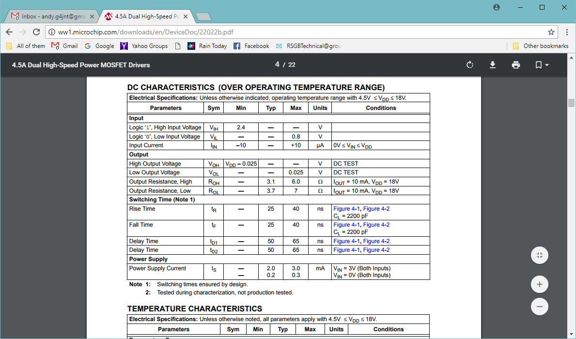
In that case you have a very odd MCP1404.    That looks like a typical CMOS threshold where the level is a fraction of the Vdd.  Often something like 0.45 Vdd ( very roughly.     CMOS guaranteed thresholds are usually specified as, IIRC,  <30% and > 70% of Vdd   (which requires a wider pk-pk when AC coupling to a mid biassed input for guaranteed operation than 'TTL'   levels do.)

The MCP14E4 (and the MCP1404 whose data sheet I found)  show the input going to a FET amplifier then Schmitt trigger so the levels can be more carefully defined 
In fact there is a 4.7V protection zener on the input which, after a resistor clamps Vin to about 5v anyway

So for yours to switch at about 4.7V, you must have a different version.


Andy  G4JNT


On 3 January 2018 at 18:29, Chris Wilson <[email protected]> wrote:
Using a second variable current limited bench supply it switches state at 4.7V  That's with just the original 15k resistors to ground on the input pins of the MCP1404

Best Regards, Chris Wilson

On 3 January 2018 at 16:41, Andy Talbot <[email protected]> wrote:
There something odd  _ I've just checked the data sheet   http://ww1.microchip.com/downloads/en/DeviceDoc/22022b.pdf  for the MCP1404 you are using (I used the MCP14E4 slightly later I think and the thresholds are listed as slightly different.  <0.8 and > 2.4V for '0' and '1' respectively   That calls for a mean of 1.6V but not that different from the 1.8 calculated.

So don't see whay your 1.8V mid bias fails.   Stick a pot on the input  and actually MEASURE the exact input voltage at which the device switches

Andy  G4JNT

Inline images 1

On 2 January 2018 at 23:35, Chris Wilson <[email protected]> wrote:


Hello Markus / Andy / all,

Please see http://www.gatesgarth.com/amp-simplified3.jpg

I  added  2  off 86k resistors as resistive dividers as shown. Voltages
were as expected 1.87 and 1.86V on pins 2 and 4 but both driver output
pins  sat high at circa 12V . Removing the added resistors but running
the  MCP1404  on  9V  all  works fine with gate and drain waveforms as
shown here:

http://www.gatesgarth.com/resistive.jpg

Not sure why this is so....Have I misunderstood the bias at 1.8V Andy
suggested??  By e-mail:


@@@@@@@@@@@@@@@@@@@@@@@@@@
"When I said bias half way, meant half way between the two logic
threshold limits. Ie mid way between 1.3V (upper limit of guaranteed
'0' and 2.4V (lower limit of guaranteed '1') so bias at 1.8V


Not half the supply volts.


Study the data sheets and calculate. Don't just play with components
willy-nilly.


Andy  G4JNT"

@@@@@@@@@@@@@@@@@@@@@@@@@@

Thanks.

Monday, January 1, 2018, 9:38:56 PM, you wrote:

>> Any ideas please?

> As Andy said, bias half way: place another pair of 15k from the inputs (Pins 12,10) to 5V (pin9).

> 73, Markus

> -----Ursprüngliche Mitteilung-----
> Von: Chris Wilson <[email protected]>
> An: rsgb_lf_group <[email protected]>
> Verschickt: Mo, 1. Jan 2018 22:26
> Betreff: Re: LF: Si5351A syntehsiser able to fire a FET driver chip directly??


> Hello Andy,

> MCP1404 IC fitted, as soon as power to the PA FETS is applied (even
> 6V) one of the gate square waves either disappears or becomes
> extremely random. Swapping inputs to the driver IC makes no
> difference, it's one pair of PA FET's dependent. FET's work fine when
> returned to "as designed" status! Driving the driver IC through the
> 1nF caps and 15k resistors to ground. Outputs from CLK0 and CLK1 are
> 180 out of phase and seem correct. Any ideas please? Thank you!

> http://www.gatesgarth.com/amp-modded.jpg

> Monday, January 1, 2018, 11:27:20 AM, you wrote:


>> Seems an odd choice of driver chip.  A high/low side driver used in
>> a non-bootstrapped mode to drive two low-side FETs


>> How about one of the normal FET driver chips - picking out one I've
>> used in the past, the MCP14E 3/4/5 family.   Logic level input,
>> spec. Logic '0' max 1.3V, Logic '1' min 2.4V.   So bias half way and
>> your 2.2V swing takes it into the valid range.


>> They three types are inverting, non inverting, and one of each in a package


>> Andy  G4JNT


--
Best regards,
 Chris                            mailto:[email protected]


<Prev in Thread] Current Thread [Next in Thread>