...me again on the half bridge and guard circuit ;-)
I found an interesting reading above this circuit wrote from .. G4JNT:
http://www.g4jnt.com/OverloadProt.pdf
so hopefully there is somebody here around that can answer my doubts ;-
)
But before explain my new mumbling, better to start from the
beginning..
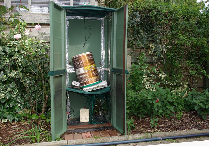
After finally had the amplifier running my worse problem for testing
was the dummy load: my Cantenna oil cooled is not the best to run for
long tests with more than 500W, so before to connect to the antenna (I
do hope it can cope with it..) I returned to the guard circuit.
Of course, as usual I took the wrong way monitoring the current
changing the load, so running the ampli at low power I started to
change the numer of turns in the link coil minimizing the return
current with load 50 ohms.
The start point was a 4:1 ratio as suggested between tank coil and link
coil thus being the tank coil a 3 layers coil of 86 turns, an available
wire made be happy with a link coil of 18 turns.
When arrived at no current the link coil had only 9 turns.. I made some
test with short or open circuit at 50Vdc and the amplifier survived :-)
but the return I guard was not so impressive: just a fraction of normal
Idd (normal Idd 1A@50V, with shorted antenna Idd 0,36A and Ig 0,5A).
The started the tests with direct rectification of the mains and was
time to test the guard circuit..
I had no time to record some datas.. a cap of the tank started to
arch.. I quickly diconnected all but one of the caps was half
vaporized! I replaced it and all (but the guard circuit) was working
again.
At the same time I was kept from the desire of a better tank coil.. the
first one was coiled on a paper tube placed on 2 pvc saddles and kept
in place from a wrap..
So after a visit to the hobby center I came back with a nice, orange
pvc pipe 100 diameter and 25m o 2.5mm² electric wire.
I prepared a new, neat tank coil with 2 nice supports. As usual is
better to cut the excess of turns but I wanted to see what could happen
;-)
So the "old" tank coil had 3 layers of turns (89T in total) starting
from 65mm of diameter and 140mmlong; the measured inductance was 223uH
with 28pF of stray capacitance.
It was resonated at 136.2 kHz with a combination of 8x3.3nF+2x1000pF
(abt). The 3dB BW of this tank is 23.7 kHz.
The new coil is coiled on the pvc form 100mm dia, 110 mm long wit a
total of 62 turns. It is much better in apparence but.. is 285uH with
stray capacitance of 175pF!
It was resonated at 136.8 kHz with a combination of 6x3.3 nF (abt
4950pF) and shows a 3dB BW of 21.5 kHz
And now we arrive at the point.. The power supply is the same, the PA
is the same, the output xfmr is the same (15T/19T on 196 mm² core), the
load is the same but:
Vdc Idd Pout
308 1.84 585W
320 1.56 465W
I assume that the difference in the Vdc is due to a lower Idd (with no
load in both case the supply is 320Vdc)
With the old tank coil the XL of the coil make the tank circuit more in
the area of Q6, altough the 3dB BW suggests a Q of 5.7 for the old tank
and of 6.4 for the new one, but
before I start to cut turns, is that enough to justify almost 100W less
in the output?
Thank for sharing your thoughts
73 Marco, IK1HSS
----Messaggio originale----
Da: [email protected]
Data: 4-giu-2017 18.42
A: <[email protected]>
Ogg: Re: Re: R: Re: LF: Re: I: Fw: For today the FETs survived...
Yes.
You need to adjust the link so current is driven back into the supply
when
RF amps exceed the maximum that you have designed for. Up to that
point
there should be no guard current as the induced voltage in the link,
when
rectified , is less than the supply.
If the link coupling were to be perfect, ie it behaved as a
transformer,
then at full power into your designed load the voltage across the tank
coil
would be Q * Vdc * 4/pi * SQRT(2) (since you calculated Rload this
way). The SQRT terms comes from the DC being the peak
So the turns ratio (for perfect coupling) if made equal equal to 1 : Q
* 4
/ pi * SQRT(2) ,will start to generate load current just as maximum
output
is reached.
But things aren't perfect; the mutual coupling is never 1 in an air
wound
coil (mine is about 0.6), the rectification doesn't give exactly peak
volts, so you have to experiment, changing the link turns until you get
the
limiting you want. Fortunately it scales with DC volts, so guard
circuit
testing can be done at low supply / power out.
'jnt
On 4 June 2017 at 16:47, [email protected] <[email protected]>
wrote:
> heyheyhey..
> now I'm testing with the new coil still at 50Vdc ;-)
> ops I was forgetting: without dissipator :-)) just with the mounting
> alu block it runs at room temp, maybe it is worth later at full
power!
> The
> picture of Andy is not in thema: is the consequence of qro ampli on
> undersize external loading coil :-)
> By the way when this ampli will finally run on the antenna I need to
re-
> size the variometer because it warms already with 250W..
>
> Also the new tank coil with 2,5mm² wire after 1 hour has a bit of
> fever.. but is not warm as the former.
>
> Just a quick question Andy: speaking of the guard circuit, if I read
> Iguard whithout mismatch is correct the assumption that the link has
> too many turns?
>
> Alan: I'm vintage.. and I'm sure I have a variac in the basement :-)
> thanks for the hint ;-)
>
> Thanks all for the psycological and praxi help !!
> Marco
>
> ----Messaggio originale----
> Da: [email protected]
> Data: 4-giu-2017 17.49
> A: <[email protected]>
> Ogg: Re: R: Re: LF: Re: I: Fw: For today the FETs survived...
>
> Something like this ...
> http://www.g4jnt.com/QRO_LF_DoesThis.JPG> 'jnt :-)
>
>
> On 4 June 2017 at 16:25, Chris Wilson <dead.fets@gmail.
com> wrote:
>
> > Hello Alan,
> >
> >
> > No, what he needs is a video camera, and the courage
to post the
> > result here for scrutiny, we need a bit of fun now and again ;)
> >
> > Good luck Marco, what's the worst that can happen.... :)
> >
> >
>
>
>
>
>
|