On Sun, Jul 14, 2013 at 12:57:44AM +0200, Stefan Schäfer wrote:
> Of course the plate is
> at one potential, just as the grounded pole. So the equipotential
> lines in the sketch will go a different way when the probe is placed
> on the top of the pole.
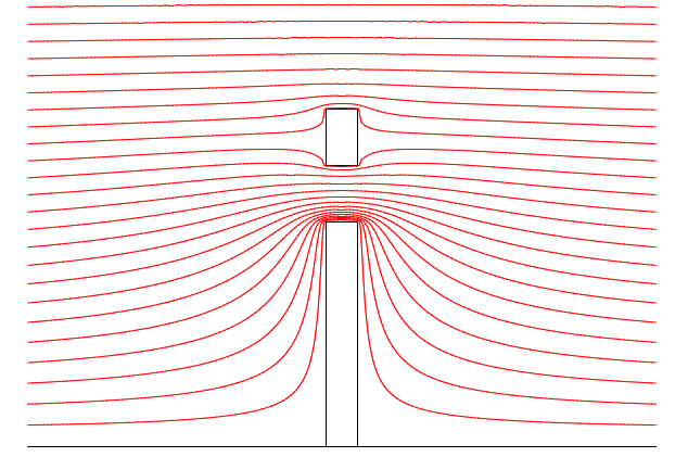
Attached is a plot of the equipotential lines in the case of a pole
with some probe (quite a big cylinder in this case) above it.
In contrast to my earlier picture, this one is not a hand-drawn sketch,
but it is a (numerical) solution to Maxwell's equations (which in
this simple case simplify to Laplace's equation).
It is still a simplification of course: in reality there must be
some circuitry between pole and probe, which will further disturb
the field a bit. But a thin wire will do so much less than the pole.
> I meant that the optimal position of the
> probe must be there, where the density of the equipotential lines
> (and so the E field strength) is as high as possible,
I don't think so. When there's a pole but no probe, the equipotential
lines are densest just above the pole (there they are compressed most).
However, those lines just above the pole are the ones which are at the
lowest potential (follow them to the left or right and you see they are
close to ground).
A little bit higher the equipotential lines are less dense, but these
lines are at a much higher potential, so putting the probe there gives
a much higher output voltage.
> so that the
> capacity against the far field is as high as possible and the
> capacity to the grounded pole is as low as possible, so that the
> capacitive divider is optimized.
As noted above: the equipotential lines are densest just above the
grounded pole, but that's of course also the place where the probe's
capacity to the pole would be largest.
So again, that's not the best place.
73, Pieter-Tjerk, PA3FWM
 pole-and-probe.png
Description: PNG image
|