Hi Rik,
No, i do not have any filtering yet. And i do not even know the
impedance level of the PA output / antenna input. I assume, it is below
50 Ohm.
Let me calculate:
With the used PA ferrite core and frequency i get about 3V per turn
(the core goes into saturation starting <8 kHz at 3V/turn) and i
have about 16 turns, so abt 48V. If the power is 300W, the Z = 48^2/300
= 7,68 Ohm. I =P/U=300/48=6,25A. So, the Z could be increased a little
but it is OK for this power.
I watched the waveform of the coil voltage with an oscilloscope and it
looks reasonable OK for me:
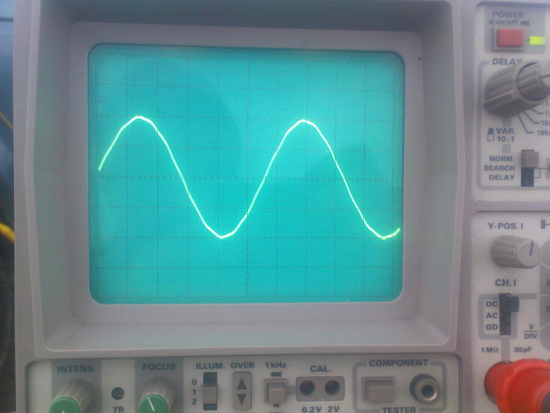
It should be mentioned that it was measured with a 1:100 probe, so a
loosely capacitive coupling was necessary (just abt 10cm wire connected
to the probe and placed in the E-field of the coil). This acts as a
highpass, so the harmonics are even overemphasized. In other words: The
real signal even looks more sinous like and this appeases my conscience
;-)
73, Stefan/DK7FC
Am 06.04.2010 11:53, schrieb Rik Strobbe:
Stefan,
about high efficiency
switched PA's: do you have any LPF between PA and antenna ?
This would require some
quite impressive inductors in the mH range at 50 Ohm.
Going to lower impedances
(8 Ohm) results in more conventient L values, but then you need large
capacitors (1-10 uF range, not really a problem) but impedance
matiching may be more critical.
Or do you rely on the
antenna for harmonic surpression ?
73, Rik ON7YD - OR7T
|
|