Dear Jim, LF Group,
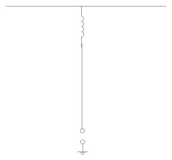
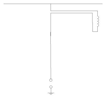
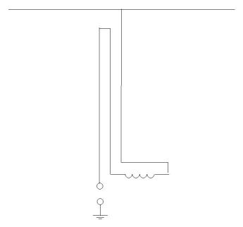
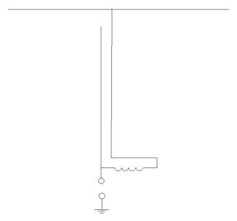
I also had difficulty in understanding how it works. I therefore tried to
construct it in 4 steps. They follow here and I hope they explain the idea
without further text. Please read also what Peter Martinez
73, Dick PA0SE
Topload 1.jpg
Topload 2.jpg
Topload 3.jpg
Topload 4.jpg


At 15:38 20-4-06, you wrote:
Dear Dick, LF Group,
I am puzzled as to how the top-loaded vertical antenna plus stub is
supposed to operate. In Fig 1, the elevated loading coil is in series
between the vertical element and the top loading, which is perfectly
reasonable ? but I can?t see how the stub in Fig 2 could produce an
equivalent series inductive reactance, especially since one terminal of
the stub is unconnected.
I can see that Dex?s antenna works (I presume the arrangement in Section
2.12 of ON7YD?s antennas page), but I don?t think it is equivalent to an
elevated loading coil. The vertical wire from the hot end of the loading
coil to the top loading section will be at high voltage along its whole
length, leading to much the same displacement currents flowing to ground
and in the mast, and therefore the same current distribution, as would
occur with a conventional inverted-L with a ground-level loading coil.
This contrasts with a top-loaded vertical with elevated loading coil at
the top of the vertical section, where all the vertical part of the
antenna is at low RF potential, and only the top loading section carries a
high RF voltage. The main effect of using the mast and the additional
vertical wire from the top of the mast to the cold end of the loading coil
as part of the antenna system would seem to be to add their distributed
inductance to the cold end of the loading coil. In other words, you would
achieve an almost identical result by grounding the cold end of the
loading coil to the bottom of the mast, and adding some extra turns to the
cold end of the loading coil.
Cheers, Jim Moritz
73 de M0BMU


|

