Hello Peter,

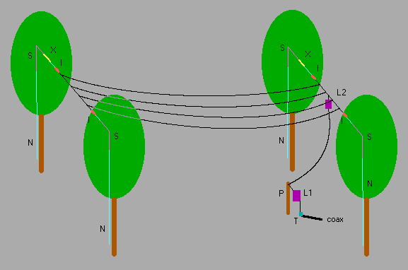
attached you find a drawing of my antenna. As you will see I not much of an
artist but I hope the picture gives you an idea how my antenna is constructed.

Some explanation :

N = nylon rope (120kg breaking force)
S = PVC coated steel rope
I = insulator
X = elastic material, it's the stuff you use fix fix a basket on the back
of a bike or on the roof of a car (sorry, I don't know the correct English
word).
L1 = base coil (variable, +/- 1.8mH)
L2 = top coil (+/- 2mH)
P = small wooden pole (abt. 2m)

The hight of the antenna (at the ends) is 11m there is about 1m 'sack' in
the middle.
The antenna is supported by 4 birch trees of about 15m high and apart from
the 'electrical challenge' to maximize the effeciency of the antenna there
was also a 'mechanical challenge' to make the antenna survive strong winds.
In the beginning I had 2 problems :
- rope breaking because of strong wind
- rope breaking because of 'friction' with the trees
The first was solved by inserting the elastic material, in the normal state
each is about 0.8m long but it can stretch to over 2m without breaking.
The friction problem was solved by placing some short pieces (about 3m) of
PVC coated steel rope where there is friction with the branches.
The antenna is up now for 1 year without being destroyed by winds (fingers
crossed).
Regarding the antenna efficiency was my main problem the high loss
resistance. When I started on LF (early 1998) I measured a loss of 220 Ohms
! Gradually the ground network was improved from 6 short radials (10 to 20m
each) on the ground to a complex system of 6 groundrods (galvanized steel,
2.5m deep in the earth) and about 150m of galvanized iron wire
interconnecting all the rods and burried about 20cm deep in the ground. But
even this groundsystem the loss resistance is still 120 Ohms. Further
exstensions of the ground system gave little or no reduction of the loss
what make me believe that at this moment the loss is mainly in the many
(several hundreds) trees surrounding the antenna rathyer than really in the
ground.
An unexpected result was achieved by placing a part (about 50%) of the
loading coil at about 10m height. The expected gain (calculated and
simulated) was only about 0.5dB but several tests and measuement showed an
improvement of 4 to 5dB.
A possible expanation for this unexpected gain is the fact that the voltage
on the vertical part is reduced by about 50% while the topload voltage
remained almost unchanged. This would mean that the unwanted 'coupling' of
the antenna to the many surrounding (vertical) trees comes mainly from the
vertical part of the antenna and by reducing the voltage on the vertical
part also this loss is reduced. The strange thing is that I did not achieve
a higher antennacurrent, the current even dropped slightly (from 1.9 to
1.85A) probably because of the extra loss in the elevated coil (since this
coil had to be very light I used thin wire).
With about 450WF power I get an antennacurrent of about 1.85A, estimated
ERP is about 100mW. But despite this very modest ERP I managed to work over
70 stations in 17 DXCC countries over the past 2 years. This might
encourage other hams to become active on LF, even when they have only
limited space.

73, Rik  ON7YD

|

