Return to KLUBNL.PL main page
| To: | [email protected], [email protected] |
|---|---|
| Subject: | LF: Direct Upconversion from audio |
| From: | Andy Talbot <[email protected]> |
| Date: | Mon, 25 Jan 2016 10:37:04 +0000 |
| Dkim-signature: | v=1; a=rsa-sha256; c=relaxed/relaxed; d=gmail.com; s=20120113; h=mime-version:date:message-id:subject:from:to:content-type; bh=+3MWMMGkvpPdblBxkadyGlE/Bn/Bysk1EQimbD2LIh4=; b=jUHw3PRJ4bqE2gNE409ro158N7l5OBHr/uv5qWiseuyH9muxpWtDbjB8boPYj/xqtF 70Q8ym8WpYsle7+4L9FNd0kZYyCCG2WNbouVG5JaCyyfHMETWQMA9gfHhJ10F9/sbq5S nkQt1VYgNn+f4HckU4+/L31PqT9OZhCajdLXoXVSpTEmNSv9LHWkqTNMZt8KF/RFw0Dg 9MzAHZny9uMobTGo4jrGcxwoH6LVRHhuxwyD5NpL6bqQy9Hi9aVKTv+hySvBS8O/zfw8 SErxlHEzyOPHeqzDJwSSlHDrkmyLioh9apmkyx5yAH7rJAKwR/h3dlzdDiOlWaG5pKw0 UsWQ== |
| Reply-to: | [email protected] |
| Sender: | [email protected] |
|
As several readers will appreciate, I have been a proponent of direct upconversion from audio to RF for some time using image cancellation and quadrature upconversion techniques. These are particularly valuable where audio bandwidths are low so the required 90 degrees of phase shift on the input audio is easily obtained. (I'm not concerned with voice signals here, with their need for polyphase or DSP Hilbert transformers) http://www.g4jnt.com/IQConverters.htm and http://www.g4jnt.com/LFUpconv.pdf give some details However, none of these single upconverters from an audio tone to the LF bands (137 and 476kHz) are really ideal as they stand, as sideband cancellation at 40 - 50dB and a carrier suppression in the region of 30 - 40dB mean that unwanted products are out of band. If the source could be generated at true baseband, ie spreading either side of zero frequency with a drive to the upconverter going down to DC they would be OK as unwanted sidebands and carrier then lie on top of the wanted signal - where -30dBc image products are not an issue. Even -20dBc here is not going to cause problems. Every mobile phone does it this way My Latest upconverter, currently in breadboard form, is a two stage one, first of all converting an audio input centred on a particular carrier down to baseband in a quadrature downconverter. The I/Q audio is generated in a PIC allowing several discrete audio centre frequencies to be accepted - or a tuneable oscillator could be added. The quadrature baseband outputs are low-pass filtered in op-amp filters with a cutoff of around 200Hz and applied to the second stage upconverter which uses a FST3253 bus switch as a quad mixer and 74HC74 quadrature source. This part of the upconverter is identical to that in Figure A1 of the LF Upconverter reference given above. A photo of the breadboard can be found at http://www.g4jnt.com/DropF/lfupconv3_breadboard.JPG Many readers will no doubt recall "Third method SSB generation" Attached to this email (if it gets though) is a screenshot of the upconverted signal from the WOLF GUI software running at quad rate 40B/s, generating at a centre frequency of 1.5kHz If not attached it can be found at http://www.g4jnt.com/DropF/lfupconv3_wolf40bps.png . The only out of band signals visible are the first stage LO spikes at +/-1.5kHz something like 90dB below the wanted output. When the audio is detuned by a few tens of Hz, sidebands appear, but are generally in the order of 70dB down Now the acid question........ Once fully developed, I could be persuaded to put the entire design onto a single PCB and if there is enough interest have this made commercially and make PCBs available. This would be subject to the following caveats: There will be no RF LO, you'll need to do your own 4X input signal, from a crystal oscillator, DDS etc. Output filtering is not included. The use of a switching gate mixer means odd order harmonics of the RF LO are very strong and must be removed with a low pass filter appropriate to the band of interest. I could place pads on the PCB for filter bread boarding. Construction will be in SMT - I use nothing else, and haven't done any wire-ended construction now for nearly two decades. So you'll just have practice SMT soldering and accept the facts of life. All the ICs are basic SOIC devices with 1.27mm pitch, and components are 0805 or larger, so even the "older" constructors (like me, now, I guess) should be able to manage them. In fact, even those SOIC packages themselves look a bit dated now compared with the TSSOP and QFP packages I regularly use. In order to gauge interest in a) bothering to lay out all bits on a single PCB, or b) having it made commercially, could I get an idea of who / how many would be interested. Please reply directly to me to avoid clogging up these groups unless you have comments applicable to a wider audience. I just want a feel if it would be worthwhile. It will be several weeks before things are finished and written up, and then another few weeks for PCBs. Cost each will be consistent with all other PCBs offers of similar size - I use a professional good quality UK based supplier, and don't try to cut costs on cheap Chinese PCB manufacture; however good others claim they now are. The PIC based I/Q source for the first LO uses a 12.288MHz crystal from which can be derived audio LO frequencies of 500, 600, 800, 1000, 1200, 1500, 1600, 2000 be selected by links or a switch. Another link allows LSB/USB selection (always useful to overcome Murphy) Viewers of the photo will observe how I originally had a 74HC74 based audio quad generator, then replaced it with the PIC one on the piggy-back PCB Andy G4JNT 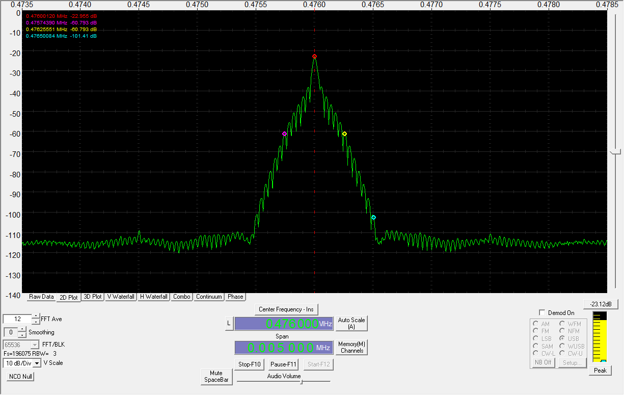 |
| <Prev in Thread] | Current Thread | [Next in Thread> |
|---|---|---|
| ||
| Previous by Date: | RE: LF: HGA22?, Laurence KL7 L |
|---|---|
| Next by Date: | Re: LF: Direct Upconversion from audio, Jacek Lipkowski |
| Previous by Thread: | LF: HGA22?, Laurence KL7 L |
| Next by Thread: | Re: LF: Direct Upconversion from audio, Jacek Lipkowski |
| Indexes: | [Date] [Thread] [Top] [All Lists] |