Hi Marco,
There are several ways you can calculate, approximate or (best)
measure the capacitance of the antenna @ 137 KHz, and from this capacitance the
needed coil inductance follows.
I have an AIM4170 vector antenna analyzer, so
I was able to measure the capacitance of the antenna
directly:
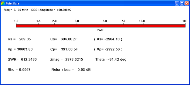
From the 395 pF the needed series L can be calculated. Just as a
sanity check I made a series L with a FT140-77 toroid. Measured L of this
inductor was 3.51 mH.
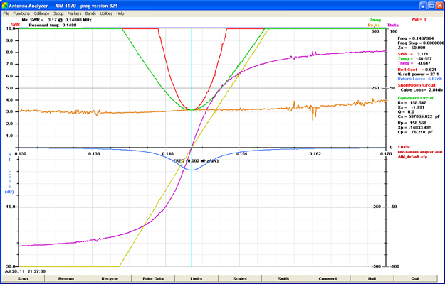
Results were quite accurate, resonance frequency was 146 KHz. So the
Variometer should indeed have an inductance around 3.5
mH.
If you don’t have equipment to measure the antenna directly It is
still relatively easy to determine the needed inductance. Start with a first
approximation of the antenna capacitance. You might do this with MMANAG-GAL (or
just take a guess between 200 and 500 pF depending on the antenna).
Be aware
however that the outcome of MMANA-GAL or any other program will lead to a
(sometimes significant) underestimation of the capacitance with antennas that
are very short with regard to the wavelength. It looks like environmental
factors that you can’t incorporate in the input (wire through part of the house,
proximity to trees, ground etc) have a much bigger impact here. My 137 KHz MMANA-GAL modeling showed a
calculated value of 208 pF, which is half the measured value. At higher
frequencies the calculations are much better (at 500 KHz only 30%
underestimation, at 3.6 MHz only 10%).
With the first approximation determine
the L you need for resonance at 137. Create this L with a (for instance)
FT140-77 toriod and put this in series with the antenna. Fire up you signal
generator and O’scope en determine the resonance frequency. Now you can
calculate the second approximation of the antenna capacity. (remember that the C
is frequency dependent). If the
resonance frequency is not too far from 136 KHz it is probably already good
enough for the design of the variometer.
Regards,
Minto pa3bca
Good morning Minto,
I built my 137KHz
antenna and loiding coil on the base what i heard from other OM's and by try and
error. I'm very interrested haw you have measured that you need a 3.5mH
coil?
Something you can share easily?
Many thanks
Vy73
Marco,
DD7PC