>The secondary winding is made of insulated coax, two turns are full
screened as they pass through the cores / >tubing, but each turn has the
braid cut at the hot end and *joined to the two ends of the secondary*,
----- Original Message -----
Sent: Tuesday, February 09, 2010 6:10
PM
Subject: LF: PA matching oddity
Has anyone got practical experience of the output matching transformers
used on MOSFET PAs - I've got a confusing one here?
I recently acquired some big HF PA modules, each rated at over 1kW
out, and made up from 8 MOSFETS, RFPP53 types, roughly equivalent to
MRF140. It runs from what is more than likely a 50V rail. The
modules were part of an industrial RF heater running at 13.56MHz, but the
design is wideband(ish) with the normal ferrite matching
transformers at input and output. Which is where I may be missing
something - they may not be quite so normal...
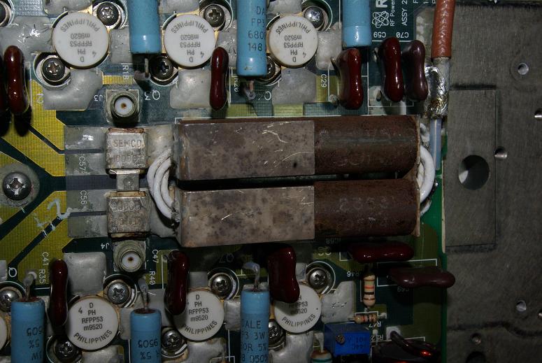
The output transformer has a slightly different topology to designs seen
before - such as those given in the Motorola handbook. The
secondary winding is made of insulated coax, two turns are full screened as
they pass through the cores / tubing, but each turn has the braid cut at
the hot end and joined to the two ends of the secondary, with the third
turn consisting just the inner conductor with no braid over it.
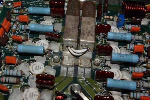
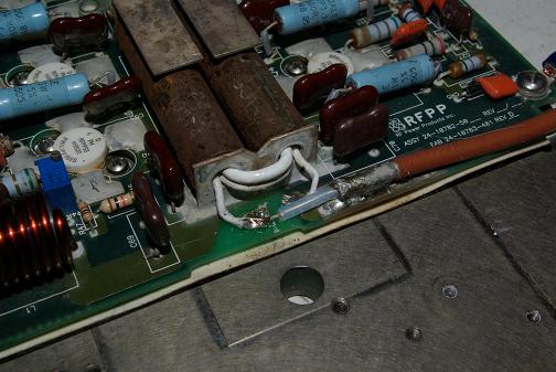
All three turns (two of coax plus the single core) sit inside the usual
single turn primary made up from brass tube, surrounded by a pair of ferrite
cores with a connection at the far end. A diagram can be
seen at
http://www.g4jnt.com/pamatch.gif
Now, the bit that doesn't seem right...
the impedances don't work out properly...
Assuming it is designed to run into 50 ohms, a 1:3 transformer will
present a load of 5.56 ohms to the push pull devices. From a
50V rail this should result in a maximum power output of 2*(50^2)/5.56 = 900
Watts. (Sanity check, a single ended design at half
the Rload = (50^2)/ 2 / 2.78 = 450 Watts each- normal push pull PA
calculation). Which is not 1kW and is only an absolute theoretical
maximum, anyway.
BUT, if the transformer were 1:4 instead, , Rload would be
3.125 ohms, Pout max would be 1600 watts which is exactly the sort of value
I'd expect to see on a real 1kW rated PA module.
Has anyone met that winding configuration before? Is it
really the 1:3 turns ratio it intuitively looks like, or is there some way the
windings could have have become an auto-transformer and be giving
1:4 turns ratio ?
If it really is 1:3 will have to assume the voltage supply may be
higher. But for a 10 year old design, sounds very unlikely.
On a quick test on the module today, running from a 10A
supply, it delivered nearly 150 Watts with the PSU current limiting and
dragging the supply volts down to 17V. Now, plugging these values into
the matching equation 2 * (17^2) / 5.556 = 100 Watts max possible, -
but I was seeing more power.
........ Extra support to the possibility of it being 1:4 - BUT HOW
?
Eingehende eMail ist virenfrei.
Von AVG überprüft - www.avg.de
Version: 9.0.733 / Virendatenbank: 271.1.1/2677 - Ausgabedatum: 02/09/10
08:35:00