----- Original Message -----
Sent: Sunday, December 01, 2002 8:27
AM
Subject: LF: Re: Series loading
coil
Hello Dick, (and group)
I've wound myself a coil on a bucket, the
inductance is a bit low at the moment, the whole thing resonates no lower
than 250kHz at present - so I've some work still to do before I transmit.
I put lots of taps in, as suggested.
But I am puzzled. In the LF Experimenters
Handbook, at the end of the description of your loading coil, it says
"by short-circuiting turns at the top and bottom
end, inductance can be decreased in steps of one turn." Why short-circuit the
unused turns? Surely that is like having short-circuited turns on a
transformer and will make the coil very lossy ?
Why not just connect the vertical part of the
antenna to the appropriate tap, and leave the others open ?
73
Hugh M0WYE
Hi Hugh
I am inclined to short cct the turns not used. I
did speak to an engineering consultant that builds linear amps at high powr
and he says it makes little difference whether the turns are shorted or left
floating. Take your pick and I dont suppose it makes a big difference which
method you use.
It is probably better to avoid capacitors to
resonate the coil, just use the tap that gives min SWR
and if you are using a 50 ohm tx o/p put a small
series coil in series with the bottom of the main coil to earth and
tap up the coax centre conductor from the earth end to get the perfect
1:1match, the earth braid of the coax goes to earth. This method does not
require any capacitor for tuning, therefore reducing any loss.
Avoid the tuning for max smoke that some suggest,
FET output transistors are very vunerable using this method, plus the fact
that RF metre readings are misleading using this method, they read the
reflected rf as well, so it is difficult to know what RF is actually going
out.
73 and gl de Mal/G3KEV
73 de Mal/G3KEV
----- Original Message -----
Sent: Tuesday, November 05, 2002 10:18
AM
Subject: LF: Series loading coil
To All from PA0SE
I also use the series coil system
for tuning and matching the aerial to the 136kHz transmitter.
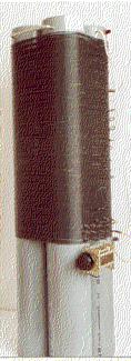
The coil
was made by bolting four 1m long and 12.5cm diameter PVC pipes together and
putting on 200 turns of 1.4mm diameter copper wire with black PVC insulation
as used for house wiring.
Inductance is 4.4mH and unloaded Q about
350.
Starting from the top I made a tap at every 10 turns by putting a
twist in the wire. Heating with a soldering iron melts the insulation that
then easily comes off to bare the wire.
The bottom 10 turns have a
tap at each turn. By short circuiting turns from the top and the bottom the
coil can be adjusted in steps of one turn. For fine tuning a variable
capacitor is in parallel with the coil. As this increases the current in the
coil and thus the loss in it (proportional to current squared!) I adjust the
coil so that only minimal capacitance is needed.
![PA0SE Coil.jpg]()
The capacitor shown started to arc over at 60W of
power. It was replaced by a vacuum capacitor rated at 5000V maximum.
When transmitter power was increased from 120W to 320W I connected the
capacitor over half the coil in order not to exceed the maximum
voltage.
The transmitter is connected to one of the turns at the
bottom end. I don't worry about SWR and simply select the tap giving maximum
aerial current (3A in dry weather).
A better picture of the coil
above can be found on page 62 of G3LDO's The low frequency experimenter's
handbook. The coil with the vacuum capacitor is shown on the cover of
the book.
73, Dick, PA0SE