|
Dear OM,
After M0BMU, G3NYK and ZL2CA I also measured the resistance of my
aerial/earth system.
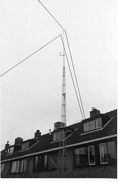
The aerial is a dipole of 2 x 20m with 11m open line feeder. See
attachment. The two legs of the dipole slope down from 18m to about 14m
at the ends and in the horizontal plane are at an angle of 100 degrees
(it is a V-beam on 20m). For LF the feederlines are strapped together to convert
the aerial into a T. The top is at 18m; the lower end of the feeder line at 7m
(ending in the shack). There the aerial is connected to the loading/matching
coil. Its bottom end is connected to the central heating system. The gas pipe
feeding the boiler in the attic leads to the gas mains that is used as
earth electrode. The gas pipe carries the full aerial current and so forms part
of the radiating system. The capacitance of the aerial is 385pF at 136kHz.
The aerial without coil resonates at 1945kHz with a resistance of
52.6 ohms. Would not be too bad for topband!
It is a rather complicated system due to the capacitance between
the vertical part (the feeder lines) and the mast and because of the central
heating system with its radiators and pipes around the house, connected to the
gas pipe that acts as part of the radiating system.
I used a Wayne Kerr admittance bridge that shows the admittance as
a conductance in millimhos (now called millisiemens) in parallel with a
capacitance in pF.
I left the C-control at zero because the aerial resistance was
measured at resonance. Jim, M0BMU, has clearly explained why this is the better
way.
As source and detector I used a Wandel & Goltermann signal
generator SP-12 and selective level meter SPM-12. They can be
interconnected so the SPM-12 also controls the frequency of the
SP-12. Because in this way source and detector are always tuned to
exactly the same frequency I could use the SPM-12 at its 25Hz bandwidth
position which helped to avoid strong signals and noise received by the
aerial polluting the measurements.
The coil has taps after every ten turns. I shortcircuited
increasing parts of the coil using those taps. (I also tried leaving the unused
part open. But as the used part became smaller and the unused part larger the
voltage at the top end of the coil increased more and more, rendering the system
extremely sensitive to hand capacitance effect).
At each tap the frequency for resonance was sought and the
conductance read from the bridge.
The resistance of the coil at each tap was found by replacing the
aerial by a variable vacuum capacitor. The capacitor was adjusted until
resonance was obtained. The high Q of the coil made tuning extremely critical;
in fact hand capacitance made it impossible to tune precisely to
the resonance frequency. Fortunately the frequency of the PS-12/SPM-12
combination can be adjusted in very small steps and this was used to tune
exactly to the resonance frequency.
The accuracy of the following R-values is limited because the
aerial wires moved a bit in the wind which caused the needle of the
detector to jump wildly about when the null of the bridge was
approached.
Frequency Resistance
kHz
ohms
126.5
40.4
132.1 36.8
136.4
34.4
141.0
32.5
146.5
31.1
152.3
28.5
158.9
27.8
166.8
27.0
175.8
26.4
185.7
25.9
198.6
25.4
214.8
24.7
235.5
20.5
261.0
16.6
296.2
14.8
346.4
14.4
423.4
16.6
73, Dick, PA0SE
|