Return to KLUBNL.PL main page
| To: | [email protected] |
|---|---|
| Subject: | Re: LF: Re: Re Loomis? & ... 12.47 Hz |
| From: | Markus Vester <[email protected]> |
| Date: | Tue, 12 Mar 2019 16:33:26 +0000 (UTC) |
| Dkim-signature: | v=1; a=rsa-sha256; c=relaxed/relaxed; d=aol.com; s=a2048; t=1552408409; bh=0nN39rfdcGcpo1dbjBa311gBnfy2iT0Fag0scGNc8fM=; h=Date:From:To:Subject:References:From:Subject; b=JCTO0cBe4aRg/O+gueIx93ItONDsYckWqpaOs/b563gQDRblN9vuF1KL92crbFcgWHdDfAkBZu5OOP9bXzpJws/lQYhhj+rg6N0R+K7QmZjUAHRk2xBBE30CqY0rmrTNDjJxr48be2fLFcgApYwiFv4aJAcD1XzpJ0niXLd16F3NO5y1NKwvoCIcVPPJu6/SRz0MWJfyx04Wov8sxupBK/tBKoNuiYs8LBMcjO8FelkRptn9pkes7bI6Et48pnmxCHYjEI8tihJ8so1WHppnXvyA+G+9ZvNhmSaVWr85NSEUqRTIBjHCymk0ijex56qs2TJj36+oIqpsr68Sh0QHtQ== |
| References: | <[email protected]> |
| Reply-to: | [email protected] |
| Sender: | [email protected] |
|
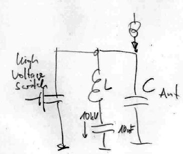
Hi Stefan, why not drive the antenna in parallel resonance? This would provide a better impedance match to the low current high voltage DC source. You'd preferably want a high voltage transistor, which could also operate in class-C with low duty cycle. From my experience, 100 uA DC seems overly optimistic. Best I got from my ant (40 m of wire) was 1 to 2 uA, which was actually during a precipitation static event (aka Grabber whiteout). In fair weather, the current is normally not measurable with a 10 Mohm millivoltmeter, i.e. less than ~ 0.1 nA. Best 73, Markus -----Ursprüngliche Mitteilung----- Von: DK7FC <[email protected]> An: rsgb_lf_group <[email protected]> Verschickt: Di, 12. Mrz 2019 16:09 Betreff: Re: LF: Re: Re Loomis? & ... 12.47 Hz Well, today: The circuit in operation on the INV-L since last night, 100% WSPR @MF. The reports on the local RX in 20m distance were between 0...+7 dB at night and -11...-9 dB in daylight. On the tree grabber in 3.5 km distance the signal was only detectable at night, levels reaching about -24 dB in average. Nothing in daylight. Where does the energy come from? It must be the voltages coming from other transmitters (DC to HF) which leave voltages up to the range of 1 V at this antenna. This RX voltage spectrum is modulated by the circuit and radiates a very weak signal. That's why the signal is about 13 dB weaker in daylight. In this experiment this is an unwanted effect. It causes some kind of offset, i.e. it lowers the SNR difference to a signal generated by cloud charges. So the 'sky-current' must be higher to become clearly observable. And it is easier to detect it in daylight. The effect should be less expressed at LF because the external voltages from other transmitters are the same but the expected voltage from a 100 uA 'sky-current' will be 475/137 higher, i.e. the system is 10 dB more sensitive for the observation of the expected effect. Unfortunately there is no LF monitor on the tree... Anyway i need to be more patient. There has been no static rain yet anyway... Meanwhile i read a bit about Miller capacity and https://en.wikipedia.org/wiki/Cascode. I built one out of two BS170 FETs somehow it does not work yet. 73, Stefan Am 11.03.2019 17:24, schrieb DK7FC: > ...the circuit is completed (attached). > First i used a simple rectangular input signal coming from the source, > over an ferrite core. The gate voltage was +-10V. But then, obviously > due to the FETs internal reverse transfer capacitance i got a 200 mVpp > output across 470 pF (tested in the lab, later to be replaced by the > antenna). I built a test source for the assumed 100 uA 'sky-current' > by using a 1 kV voltage source and 10 MOhm in series. As assumed, a > linear rising voltage was observed during the off-times of the FET. > However, together with the voltage coming over the Crss, the residual > rms value even dropped! Thus i had to reduce the gate peak-peak > voltage and ended up with the circuit shown in the attachment. There > is a DC offset and the AC component is as low as possible. The reduced > the unwanted voltage 8 mV. > Then, 50 mV rms at 475 kHz at 100 uA DC 'sky-current'. > > How far will a 50 mV rms WSPR signal be detectable? And will the > 'sky-current' reach 100 uA at all? At least the signal strength will > rise with the square of that current, so the report are nearly as good > as a current measurement. > > 73, Stefan > > > > Am 11.03.2019 13:29, schrieb DK7FC: >> Hello Jim, >> >> Yes, indeed. >> I'm now preparing the circuit and want to set it up in the evening. >> Found an IRF820 in the 'junk box', a good choice. Or, maybe even a >> BS170 will work. It handles 60V only but i had the following thought: >> >> The ERP at a constant voltage across the antenna (say 50 V rms at the >> fundamental frequency) will rise with the sqare of the frequency (for >> electrically short antennas). But that voltage will not be constant >> in practice. It will drop linearly with the frequency ( ~ 1/f) >> because the sky-current is assumed to be constant and the charge up >> time is T/2. And, doubling the voltage at the antenna will also rise >> the ERP by a factor of 4. All in all it means the the ERP is >> constant, or independend of the frequency!? >> That means, it would be wise to select a band where many RX stations >> are watching and propagation is promising. The number of RX stations >> is higher at MF but (groundwave) propagation is better at LF. >> Since the peak voltage will be lower at MF (shorter charge-up time), >> MF is less critical. >> >> And which mode?! I think the best choice is a 100% duty cycle WSPR >> beacon. It also has the advantage that one can check the results in >> the database. And there are many RX stations, even in the groundwave >> distance and even in less than 100 km here. And i have my tree which >> can detect small differences at very low levels. >> At MF, the BS170 is a good choice i think. And it can be driven by a >> Raspi directly, maybe with a ferrite transformer in the gate-source >> path, to decouple the shack from the antenna... >> >> If that works, one could try LF. >> >> 73, Stefan >> >> >> >> Am 10.03.2019 20:18, schrieb [email protected]: >>> All great ideas in the preceding messages. >>> >>> A steady signal from the 136 kHz sky-current transmitter could >>> indicate that a data bit might be available later from the 10 Hz >>> sky-current transmitter. >>> >>> Agreed, the triggered gap sounds better than an HV vacuum relay (for >>> jitter and reliability). >>> >>> Sounds like the voltage divider doesn't need to be more than a >>> gigohm, but perhaps for future reference: a reliable 50kV 1 terohm >>> divider can be made very easily: encapsulate ten 100 gigohm >>> resistors in hard epoxy, being sure not to touch them during >>> assembly. A single linearity calibration after curing will be remain >>> valid +/- 10% for years in varying humidity and temperature. >>> >>> 73, >>> >>> Jim AA5BW >>> >>> >>> -----Original Message----- >>> From: [email protected] >>> [mailto:[email protected]] On Behalf Of DK7FC >>> Sent: Sunday, March 10, 2019 5:52 AM >>> To: [email protected] >>> Subject: Re: LF: Re: Re Loomis?& ... 12.47 Hz >>> >>> Hi Jacek, DC, >>> >>> Yes yes, i already see a new project for summer :-) >>> >>> A floating antenna will charge up to a voltage where the E field >>> strength is high enough to start partial discharges, something like >>> 20 kV maybe, depending on the wire diameters and homogenity of the >>> arrangement, also on pressure and humidity. So there will be a >>> voltage limit given by the arrangement. But a higher field strength >>> in summer will help to charge up the antenna faster, so higher >>> switching frequencies are possible. >>> >>> One could build/use a triggered spark gap, >>> https://en.wikipedia.org/wiki/Trigatron, this will hold higher >>> voltages and you can connect the trigger directly to a ublox GPS >>> module running e.g. at 3 Hz :-) I think this will give a lower >>> jitter than when using a vacuum relay. >>> Could this work over my 3.5 km path if i use my inv-L? I don't think >>> so. >>> The time to integrate will be to short and there will be much QRN >>> during such an experiment, so the SNR will be very low. Currently >>> (at 12.47 Hz) i already have 15 kV DC available... >>> >>> Anyway, interesting questions, there is something interesting to learn. >>> Maybe i will do a few experiments in summer. Building a HV divider >>> and measurement should be no problem... >>> >>> 73, Stefan >>> >>> PS: Assuming 100 uA constant current 'coming from the sky', my 470 >>> pF antenna would charge up with 213 kV/s, so it would be possible to >>> switch at 10 Hz and get a 21 kV 'square wave'. Maybe the harmonics >>> could be detected easier than the fundamental frequency. >>> At 137 kHz it would be 1.5 V only (0.53 V rms). This can be switched >>> with a normal FET! Imagine we would switch the antenna permanently >>> at, say 136.172 kHz, using a FET and a ublox GPS module. Then, as >>> soon as the field strength is high enough, we would see a carrier on >>> the grabbers? We need to try that out! Amazing! What a great hobby >>> we have!?! >>> PPS: For this experiment, the antenna can be series resonated, which >>> would help to concentrate the energy to the wanted spectrum... >>
|
| <Prev in Thread] | Current Thread | [Next in Thread> |
|---|---|---|
| ||
| Previous by Date: | Re: LF: Re: Re Loomis? & ... 12.47 Hz, DK7FC |
|---|---|
| Next by Date: | Re: LF: Re: Re Loomis? & ... 12.47 Hz, Jacek Lipkowski |
| Previous by Thread: | LF: Re Loomis? & ... 12.47 Hz. Literature and patents., James Hollander |
| Next by Thread: | Re: LF: Re: Re Loomis? & ... 12.47 Hz, Jacek Lipkowski |
| Indexes: | [Date] [Thread] [Top] [All Lists] |