Hi Stefan, LF,
we're
not
just
playing around... I would rather consider this an original
scientific experiment, perhaps worth proposing as an research project
in environmental physics ;-)
Frequency stability will not be
much
of an issue. Throughout the night, the 5th order resonance moved around
by two or three pixels, approximately 100 Hz or twice its own width. So
after having found the right frequency in the first place, we could
just let the transmitter sit on the exact QRG for many hours without
loosing much signal (even more so for 1.7 kHz).
Here
are
some
back-of-the-envelope calculations for your institute antenna,
grounded at the other end: Assuming a loop area of around 2000 m^2,
radiation resistance at 8.5 kHz would be 0.17 microohms. Given the
cross section of your horizontal wire and the lightning protection
system, you could perhaps run up to 100 A loop current (maybe too
optimistic?), which would give 1.7 mW radiated power - comparable to
your first kite experiments and surely enough to be received here
easily even without any resonance enhancement. At 1.7 kHz, radiated
power would be 625 times smaller (2.6 uW) but probably still detectable
under quiet conditions. Estimated inductance would be around 110 uH
or 5.9 j ohms at 8.5 kHz.
Depending on the quality of the
grounding installation you will probably require some kilowatts drive
power, and a suitable array of parallel FKP's to cancel inductance.
Alternatively, the company I work for produces some cool fat MRI
gradient power amplifiers, designed to deliver hundreds of amps into
inductive loads ;-)
On the receive side here, my
biggest
problem at low frequendcies is railway interference - - this is one reason to start at higher
frequency before going to 1.7 kHz. As the incident wave will be
circularly polarized I could try to rotate the receive loop to minimize
local QRM. An interesting and favourable point is that your TX loop
will be pointing north-south, which will minimize "contamination" by
direct groundwave to my direction. However
I
do
not know what the lateral extent of the resonance mode is, in
other words how much enhancement we will still get at 180 km distance
or 45° elevation.
Alternatively
you
could
try to detect the tweek resonance using your garden receiver,
close enough to provide true vertical skywave incidence and full cavity
resonance enhancement. To be able to see the skywave, you will only
have to turn the receive loop carefully to null direct nearfield
inductive coupling.
One last point for dreamers: The
counterrotating polarized component which is not reflected will
penetrate to the magnetosphere and may propagate as a whistler wave.
This could theoretically be received at the magnetic conjugate point,
somewhere near Madagascar...
73, Markus (DF6NM)
Sent: Saturday,
July
18, 2015 10:51 AM
Subject: Re: VLF:
Tweek
mode resonances
Hello Markus,
Thanks for your observation and article! :-)
Most interesting.
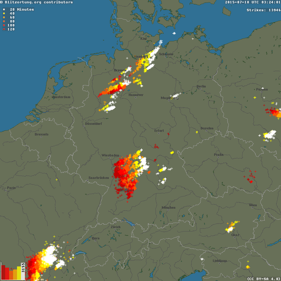
I can indeed confirm there were a number of cloud-cloud lightnings last
night, up to 20 per minute were visible at times.
My VLF loop in the garden is a vertical hula hup circle with 80 turns
of wire inside. About 80 cm diameter. The receiver is the stereo
soundcard, making the stream for MF+VLF.
This observation reminds me (of course) on our idea to try to transmit
(clap our hands!) on about 2 kHz, the 150 km band :-) with a vertical
loop and receive with a vertical loop! I should check if it is possible
to reach the roof of the other building, where my TX-antenna is
mounted, to ground the wire, i.e. to build a vertical loop!
BTW, yesterday i officially requested a permission by the chief of the
local forest district to put some electronic equipment on a high tree
in the forest!! Solar, modules, batteries, WLAN-antenna and a box
including electronic equipment. The location is 3 km distant from the
institute, much more distant to man made noise sources then my garden
and still in a direct view to arrange the WLAN-link! No answer yet...
The 5th mode near 8.5 kHz? Well, that resonance isn't really stable
over the frequency, so it is not possible to try modes like DFCW-6000
or even 600. So the possible distances would be rather small. But woth
to try playing, obviously :-)
73, Stefan
Am 18.07.2015 06:50, schrieb Markus Vester:
The screenshot http://df6nm.bplaced.net/VLF/spherics/dk7fc_VLF_150718_1326.jpg shows a number of narrow tweek-mode resonances at multiples
of 1.72 kHz. These are obviously spherics from nearby lightnings,
bouncing multiple times vertically between the ionosphere and ground
(much the same as clapping your hands between two parallel brick
walls). The resonances are rather sharp indicating a high Q-number (ie.
around 100 bounces until decay). They are visible up to about 20
kHz, showing unusually small damping of vertical incidence reflections
at these frequencies. There is a small variation of resonance frequency
over time, reflecting the variable height of the ionospheric
ceiling. The fundamental resonance at 1.7 kHz is probably not visible
due to the frequency response of the loop and receiver.
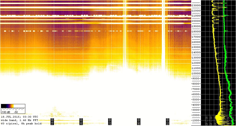
The tweek resonances were
received
on the loop antenna in the garden but not on the E-field antenna of the
(somewhat whitened out) city grabber http://df6nm.bplaced.net/VLF/spherics/dk7fc_wideband_150718_0330.jpg. This corroberates the notion of near vertical
incidence and horizontal H-field polarisation. According to the
literature, tweek tails are usually circular polarized as only one
sense of rotation exhibits a high reflection coefficient. They are
predominately excited by horizontal current components in intra-cloud
lightnings.
Of course the resonances
will also
be there in quiet nights without spherics, so they could probably be
employed to enhance fieldstrength (up to a factor of Q) for
medium-range VLF communication experiments using magnetic transmit and
receive antennas. When Stefan still had his earth dipole we already
discussed a 2 kHz tweek-mode experiment, which for various reasons
hasn't taken place yet. Now it looks like one could even employ the
fifth mode near 8.5 kHz...
All the best,
Markus (DF6NM)