|
Hi Stefan,
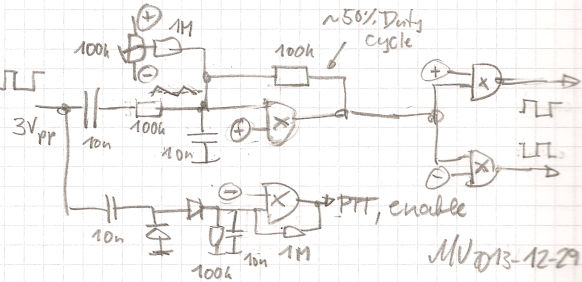
here's a quick sketch of how I would go about it.
You wanted XORs so here's one with XORs ;-) But in this circuit they serve
basically only as inverting or noninverting opamps, depending whether their
other input is connected to the (+) supply or (-) ground.
The top left part tries to pull the duty cycle
close to 50%. The AC voltage is reduced, and with the negative DC
feedback the comparator threshold settles to a point where the avaerage
output is at half supply voltage (eg 2.5V). BTW this is the opposite
function to the "duty cycle amplifier" which I use in my automatic LF
variometer df6nm.bplaced.net/LF/pictures/AutoTuner.zip .
The output circuit is an inverter used for
inverting one of the drives ;-) The pair of XORs should equalize the
gate delay.
The vox circuit at the bottom with the
rectifier is straightforward, including a bit of hysteresis introduced by
positive feedback.
Best 73,
Markus (DF6NM)
Sent: Sunday, December 29, 2013 2:43 AM
Subject: LF: VLF exciter
Am 28.12.2013 23:33, schrieb Markus Vester:
PS Any progress on bypassing the
divider in your VLF transmit chain?
Aaah,
no, i forgot that. So i cannot transmit OP32 on VLF because it would be
incoherent then. So i have to key the PA via a VOX and OP32 tones, still
:-/
In this H bridge PA config, an exact 50% duty cycle isn't needed,
so i may actually remove the divider. But then i need a solid and defined
input signal wave form! How do i get an inverted signal then? A transformer
isn't possible since i like to have a wide frequency range of the PA. So far
it works from 10 Hz to > 100 kHz. With the frequency divider, the wave form
can be quite distorted, no problem unless the peak reaches the necessary
voltage level. So maybe it is better to build the VOX circuit instead? Also i
want to leave the PA circuit as it is, for nostalgic reasons :-)
Or do you
have another idea? I remember that circuit with the XOR gates...
73,
Stefan/DK7FC
|
 vlf_dutycycle_inverter_vox.jpg
Description: JPEG image
|