|
Roger,
attached beneath are a couple of mails on the
subject which I had posted on blacksheep in 2010. Here's a summary of the
formulas:
- An earth antenna forms a magnetic
loop antenna between the wire and the subsurface return
currents:
Aearth = length * effective depth = length * skin depth in ground / sqrt(2).
Thus the depth scales inversely with the
squareroots of frequency and ground conductivity, and is usually a few tens
of meters at VLF. Somewhat
surprisingly, this still holds true if the wire length is
much shorter than the ground skin depth.
- The radiation resistance of the loop is
Rrad = 31171 ohm * area^2 /
lambda^4,
allowing you to calculate the radiated power in the
main lobes as
EMRP = current^2 * Rrad
- The effective area of the earth
antenna can be measured simply by comparing the received voltage
from a distant transmitter to that from a small nonresonant wire
loop:
Uearth / Uloop = Aearth / Aloop
Alternatively, using a signal of known
fieldstrength E, the loop area can be calculated by
Uearth = E * Aearth / (lambda /
2pi)
If the loop antenna is not optimally aligned
with the wire towards the other station, a cosine
directivity factor should be taken into account.
Best 73,
Markus (DF6NM)
Sent: Saturday, June 08, 2013 6:15
PM
Subject: LF: ELF antenna ERP
calculations - request for resend of information
Some months ago - time flies, so it may
have been last year - someone kindly sent me a copy of a paper, or at least a
formula, to work out the radiated power (as opposed to other forms of signal
transmission) from an earth-electrode pair "antenna" at ELF. I think it was
based on some of the Project Sanguine work at 76Hz back in the 1970s. I thought
I'd saved this, but cannot locate it anywhere.
If you remember sending me this data,
please would you resend it?
Thanks.
73s
Roger G3XBM
___________________________________________
Sent: Thursday, September 02, 2010 7:22 PM
Subject: Re: LF: Earth loop depth
Dear LF,
I recently discovered that I had a misconception regarding the effective
area of an earth antenna, which may be interesting to other experimenters as
well. It seems that short earth antennas are much more efficient than I had
intuitively anticipated.
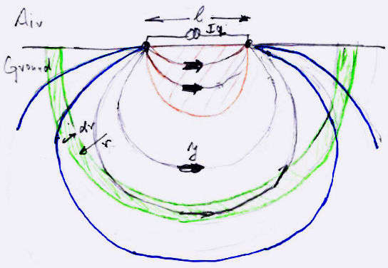
For small electrode spacing, most of the current returns through the ground
in the vicinity of the wire. My understanding was that the effective loop area
would then look similar to the a half-circle beneath the baseline, as depicted
by the red area in the sketch. This means that for small baselines, effective
loop area would scale quadratically with baseline length. This would hold until
the baseline is made so long that penetration becomes limited by skin effect in
the ground, and one enters a regime of linear scaling of area vs length.
Then I tried to calculate the magnetic moment for the non-skin effect case
based on DC current densities in homogeneous halfspace. The current field is
similar to the electrical nearfield of a dipole. Integrating depth-weighted
current densities over the halfspace volume should then give the total magnetic
moment. But this integral did not converge to an asymptotic limit, but appeared
to grow monotonically with integration volume. This implies an infinite
effective depth of a DC ground loop!
At first I looked for an error in the integral calculations, but then I
noticed that the divergence can be explained by a simple scaling argument along
the following lines. At a distance r from the dipole (current Iq times length
l), current density J in the ground scales as
J(r) ~ Iq l r^-3.
A
large half-shell (green) around the dipole has a perimeter pi r around its
equator, so there the total current would be
I(r) ~ Iq l r^-2 dr
The
contribution to the magnetic moment of the shell is proportional to its
broadside area A ~ r^2, which gives
dM(r) = I A ~ Iq l dr ~
constant.
This means that each additional shell will add the same amount of
magnetic moment, and the total moment would indeed grow to infinity if r is not
bounded by skin effect. Even though the outer fieldlines (blue) carry only a
small part of the current, due to their large cross section they still
contribute significantly to the loop area.
This reasoning also falls in line with a much easier analysis for the
receive case. Vertically polarized groundwaves have transverse magnetic fields,
which must be bounded by radial ground currents (ie in the direction of wave
propagation). The finite surface resistance of the ground creates an additional
radial electric field, which can simply be tapped by the electrode
baseline. The induced voltage (and thus effective loop area) will depend
linearly on the baseline length, no matter how short it is. Solving the
equations for equivalent depth is straightforward and gives
d_eff = (omega mu0 conductivity)^-0.5 = skindepth / sqrt(2) .
For a crude experimental test, I took a battery operated notebook to the
garden, stuck the two leads of the soundcard input into the soil, and measured
the induced voltage from the DHO signal. When going from 1.5 m to 3 m electrode
spacing, it went up by 6 dB (and not 12 dB), showing that pickup area scaled
linearly and not quadratically with baseline.
Kind regards,
Markus (DF6NM)
Sent: Thursday, September 02, 2010 7:07 PM
Subject: Re: LF: ERP calculation (revised)
Dear Roger,
thanks for sharing your results!
The directional dependence should be a simple cosine law, so going from 45°
to 0° would give you another 3 dB, or 3.8 uW ERP. Thus your total radiated power
was 2.0 uW (EMRP). At 62 km, this gives -14 dBuV/m, which should indeed be well
readable in QRSS 3 under quiet conditions.
Taking a loss resistance of 60 ohms, 4 watts would have given you an
antenna current of 0.26 A. The radiation resistance is then
Rrad =
EMRP / Iq^2 = 30 microohms.
A standard formula for loops is
Rrad =
31171 ohm * A^2 / lambda^4,
resulting in an effective loop area
A =
155m^2.
Note this is using the radiation resistance for a loop in free space, as
the effect of ground is already included in the earth antenna picture. For an
above-ground loop with a mirror image beneath it, radiation resistance would be
doubled.
Best wishes,
Markus (DF6NM)
-----Ursprüngliche
Mitteilung----- Von: Roger Lapthorn < [email protected]> An:
[email protected]Verschickt: Mi., 1. Sept. 2010, 13:41 Thema:
LF: ERP calculation (revised)
Today I managed, I
believe, for the first time to accurately measure the ERP of my QRPp
system on 137kHz. This is the method used:
- Using the E-field probe, FT817 (AGC off, gain backed off as far as
possible and a 10dB pad between the EFP and the FT817) and Spectran I went to
my usual test site 1.5km away from the QTH, 45 degrees off the main lobe of
the TX loop/earth electrode antenna.
- Measured the signal level of DCF39 on 138.83kHz
- Measured the signal level of G3XBM on 137.675kHz
- Repeated this three times to reduce errors.
- Noted the difference in FS level.
Difference in signal level =
44dB . I feel pretty confident this is an accurate figure now and
not effected by AGC and overload. Assuming DCF39 is 1mV/m here (info from
Alan Melia) then my FS at the test site is 6.4uV/m. Using the
formula ERP = (E*d)^2/49 where E = 6.4*10E-6 and d=1.5*10E3 gives an ERP =
1.9uW giving an antenna efficiency of -63dB using the earth electrode
antenna with the elevated feed and 4W from the PA. The test site
is about 45 degrees off the main line of fire of the antenna, so in the best
direction it could be 10dB (?) stronger, i.e. 20uW ERP giving an antenna
efficiency of -53dB in the best directions. Frankly I'm amazed that
anyone can copy this signal at any distance, so full marks to G3XIZ (48km) and
G3XDV (62km). Next stage is to try this arrangement for a few more days
using QRSS3 and WSPR before swapping to a full "in the air" loop and repeating
these tests. Great fun and I'm leaning as I go, which is the whole point
of ham radio. 73s Roger
G3XBM
|