Return to KLUBNL.PL main page

rsgb_lf_group
[Top] [All Lists]

Re: LF: Problem with generator to VLF transmitter - correction

To: <[email protected]>
Subject: Re: LF: Problem with generator to VLF transmitter - correction
From: "Marcin" <[email protected]>
Date: Tue, 4 Dec 2012 21:16:06 +0100
References: <003f01cdd0cd$7ba8de30$6600a8c0@dupaod6d2sep9z> <A735210EBAD6448E964A08B7E44A84C0@White> <1EB8E61D15EF47F696AC3097C512A95D@White> <[email protected]>
Reply-to: [email protected]
Sender: [email protected]
Hi Stefan, Markus, Rik, Graham!

Thanks for all your replies.

I’ll try to answer all your questions.

1.Our first club VLF tests we had in 2010. Our ODX is Jacek SQ5BPF 290km on a 500W transmitter. G3XBM’s site even mentioned this. Unfortunately, the last two years have been fruitless just because we had no driver. If the project continues with its current pace, it’s bound to get terminated.

2. The need for 180 degrees shift for duty cycle stems from the necessity of steering 2 transmitter IGBTs.

3. The 5-45% duty cycle can be regulated by the transmitter’s power.

4. Without capacitors our old antenna would resonate at ca. 17kHz. The capacitors are mica (30kV). We got our 30m mast stolen so now we just have a brand new 20m antenna as a replacement. Diagram attached.

5. Thanks for all your comments and advice on IGBT transistor connection.

6.I amaware of the difficulties with shifting time of transistors. All too often we could see them explode in 136kHz transmitters. To prevent overload we’ll use ordinary 40W, 220V light bulbs. :-)

7. The Rubidium synthesizer, I reckon, will prove a very good idea in the future.

8. There are 2*56V, 30A transformers there with diodes from a welding machine.

9. Thanks for all your comments&advice regarding antenna coil.
 
73! Marcin SQ2BXI
 
----- Original Message -----
Sent: Monday, December 03, 2012 12:26 AM
Subject: Re: LF: Problem with generator to VLF transmitter - correction

Hi Marcin,

Further suggestions:
-If you have found the resonance with the existing setup, then i would do initial high power tests with it. You will have some first with this configuration. It will be no super DX but e.g. SQ5BPF will receive you!
-I would forget about the variable duty cycle. Use a fixed 50% duty cycle. If you want to vary the duty cycle anyway there is a solution by using a stereo pot and 2 capacitors and a CD4093 for example. But there may be some transient voltage problems, as Markus mentioned.
-For initial tests, you don't need a perfect stable transmit frequency. The typical stability on an xtal of the PC soundcard is fine as long as you keep temperature variations small. SpecLab does it perfectly, also in QRSS or DFCW!
-Markus is right about the poor efficiency in the current configuration. So, for later tests i would tend to rise L and to lower C, the parallel C.
-It would be a first step to use a much bigger body for the coil. You should use at least 80cm diameter. If you use the same wire on a big water barrel, then you will get much higher L values and so you can reduce the parallel C.

It looks like the height above ground is remarkable. And 60V*50A sounds good as well. However you will have some problems to generate 3 kW with the circuit shown in the image. Anyway, have a good start!

Aah, a last suggestion: Build an amperemeter for the antenna current! This is most interesting to see and to check for improvements.

73, Stefan/DK7FC

Am 02.12.2012 23:27, schrieb Markus Vester:
sorry "(Cant+Cp)/8" is a typo, should be "(Cant+Cp)/Cant".  73, Markus 

Sent: Sunday, December 02, 2012 11:21 PM
Subject: Re: LF: Problem with generator to VLF transmitter

Marcin,
 
happy to read about upcoming Dreamers band activity! Just a few comments:
 
- 70 mH inductance seems too small for the antenna capacitance. Using capacitors (4 nF) in parallel to the antenna is unfortunately very inefficient, as only a small part of the coil current will go to the antenna. This would decrease the effective coil Q by a large factor (Cant+Cp)/8, ie about 8. It would be better to use more turns of thinner wire to bring the inductance up.
 
- according to the photo, the IGBT module seems to be wired as a half-bridge, with the transistors internally connected in series at C2E1. You would have to break up that connection to use them in grounded emitter push-pull configuration.
 
- do you want to change the duty cycle to modulate the output power? With both transistors off, the current will have to go through the freewheeling diodes, which will probably have unwanted effects on the voltage waveforms.
 
- SpecLab with samplerate correction is probably the easiest choice for an 8.97 kHz sinusoidal signal generator. But with some PC's there can be problems with sampling gaps or glitches on the output. In my opinion, an optimal hardware solution is a programmable Rubidium synthesizer, followed by a fixed divider eg /1024. Chinese second-hand FE5680-A modules are available around 80 Euro on eBay.
 
- Stefan mentioned linear AM by outphasing. For this you would need two half bridges with two independent drivers, which can be driven by two channels from a stereo soundcard.
 
Wishing the best of luck,
 
73, Markus (DF6NM)


From: Marcin
Sent: Sunday, December 02, 2012 9:42 PM
Subject: LF: Problem with generator to VLF transmitter

Hi All!
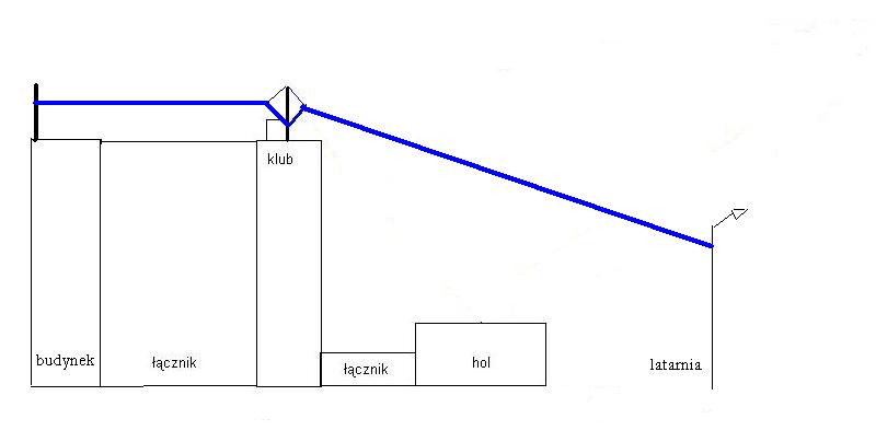
We’re building an 8,970kHz VLF transmitter at SP2KDS club.
We almost have everything in place:
 
What we still need is a generator to feed the transmitter. Required parameters are the following:
  • 8,970kHz frequency
  • regulating range +-0.05Hz
  • adjusting duty cycle of 5 to 45%, at 5% for two signals at the same time
  • two signals shifted by 180 degrees
A friend of mine has promised to build it but it’s been over a year now and nothing has happened.
Is there a software which would use a soundcard with the aforementioned parameters?
 
73! Marcin SQ2BXI

Attachment: bez tytułu2.JPG
Description: JPEG image

<Prev in Thread] Current Thread [Next in Thread>