Dear Ken, Clemens,
As I recall, Ken is using a HF wire as a VLF RX antenna. The LF/VLF source
impedance of such an antenna is basically the capacitance of the wire in
series with some loss resistance - at 9kHz, Xc will probably be several 10s
of kilohms, Rloss several hundred ohms. The source impedance is therefore
always much higher than the load impedance of Ken's sound card and/or filter
of 4 kilohms or less - so the RX sees a signal source that behaves
approximately as a constant current source, and the voltage at the soundcard
input will be (signal current) * (soundcard Zin). So the signal voltage will
be nearly proportional to the input impedance. Reducing Zin from 4k to 50R
will therefore reduce the signal voltage by a factor nearly 50/4000 -
about -38dB. Actually, if a symmetrically terminated filter with Zin/Zout =
50R is used, to achieve the designed frequency response it will be necessary
to have shunt 50R resistors at both input and output, making the overall
input impedance at the antenna terminal something nearer 25ohms, knocking
off a further 6dB of signal. Loss of 44dB in signal level may well be too
much. Also unfortunately, the antenna impedance will be much lower at
broadcast frequencies - so the current due to broadcast QRM may be
increased, depending on the circuit design, reducing the effectiveness of
the filter.
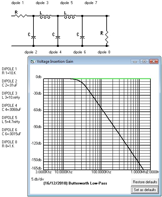
A better idea would be to design a singly-terminated filter. Connect a
terminating resistor of as high a value as possible (say 1 or 2 kohm) across
the soundcard input to terminate the filter. Then design a low-pass filter
with "infinity" source impedance, and load impedance equal to the new
soundcard input resistance. The attachment shows my first effort with the
AADE software, with 30k cutoff frequency and 1k load impedance. The 10k
source impedance isn't infinity, but is close enough for practical purposes.
I fiddled with the values a bit to get preffered values. Note that the input
capacitor C2 can "absorb" the capacitance of the antenna and feeder. E.g.,
if you connect the antenna via 10m of coax (100pF/m), and the antenna has
300pF capacitance, C2 could be reduced to 8.7nF to maintain the same
response. The same also goes for the output side - but if the input
capacitance of the soundcard is really several nF as some have found, the
filter would need to be re-designed.
Cheers, Jim Moritz
73 de M0BMU
 VLF_filter.jpg
Description: JPEG image
|