Return to KLUBNL.PL main page
| To: | "LF-Group" <[email protected]> |
|---|---|
| Subject: | LF: Series loading coil |
| From: | "Dick Rollema" <[email protected]> |
| Date: | Tue, 05 Nov 2002 11:18:01 +0100 |
| Reply-to: | [email protected] |
| Sender: | <[email protected]> |
|
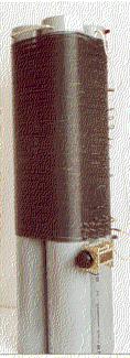
To All from PA0SE I also use the series coil system for tuning and matching the aerial to the 136kHz transmitter. The coil was made by bolting four 1m long and 12.5cm diameter PVC pipes together and putting on 200 turns of 1.4mm diameter copper wire with black PVC insulation as used for house wiring. Inductance is 4.4mH and unloaded Q about 350. Starting from the top I made a tap at every 10 turns by putting a twist in the wire. Heating with a soldering iron melts the insulation that then easily comes off to bare the wire. The bottom 10 turns have a tap at each turn. By short circuiting turns from the top and the bottom the coil can be adjusted in steps of one turn. For fine tuning a variable capacitor is in parallel with the coil. As this increases the current in the coil and thus the loss in it (proportional to current squared!) I adjust the coil so that only minimal capacitance is needed. The capacitor shown started to arc over at 60W of power. It was replaced by a vacuum capacitor rated at 5000V maximum. When transmitter power was increased from 120W to 320W I connected the capacitor over half the coil in order not to exceed the maximum voltage. The transmitter is connected to one of the turns at the bottom end. I don't worry about SWR and simply select the tap giving maximum aerial current (3A in dry weather). A better picture of the coil above can be found on page 62 of G3LDO's The low frequency experimenter's handbook. The coil with the vacuum capacitor is shown on the cover of the book. 73, Dick, PA0SE
|
| <Prev in Thread] | Current Thread | [Next in Thread> |
|---|---|---|
| ||
| Previous by Date: | LF: Re: Re: Re: Re: Siemens D2006 Selective Level Meter/Pegelmesser, g6tmk |
|---|---|
| Next by Date: | Re: Re: Re: Re: LF: Siemens D2006 Selective Level Meter/Pegelmesser, jan-martin . noding |
| Previous by Thread: | LF: Nov 6-10 LF UA6-activity, Ed Lesnichy |
| Next by Thread: | Re: Re: Re: Re: LF: Siemens D2006 Selective Level Meter/Pegelmesser, jan-martin . noding |
| Indexes: | [Date] [Thread] [Top] [All Lists] |