Dear LF group,
To try and gain a bit more insight on the functioning of small LF
antennas, I measured the loss resistance of my inverted L (8m
high, 40m long) over a range of about 9kHz to 553kHz. I used the
SPM-3 selective voltmeter and PS-3 tracking generator in
conjunction with the SFZ-1 impedance bridge attachment and a
decade resistor box to measure the resistance of the antenna
resonated at different frequencies using various series loading
coils. I found for various reasons that measuring the impedance of
the tuned antenna worked much better than trying to balance the
resistance and capacitance of the un-tuned antenna with the
bridge; however, the resistance of the loading coil was a
significant fraction of the total resistance, and to determine the
loss resistance of the coils I repeated the measurements with the
antenna disconnected and replaced with a calibrated air-variable
capacitor adjusted for resonance at the same frequency. This also
gave a measurement of the antenna capacitance.
The results are listed below in the order
f, kHz;R(loss), ohms; C(ant), pF:

9.16,   295,    336.4;
10.4,   270,    336.4;
12.4,   235,    336.6;
14.4,   219,    337;
17.3,   183,    336.5;
19.9,   170,    336.6;
24.0,   145,    336.4;
27.4,   129,    336.3;
31.9,   113,    336;
36.8,   103,    336.4;
41.8,   93,     336.4;
52.0,   81.5,   336.6;
60.9,   69.5,   336.6;
68.9,   71,           336.8;
83.3,   61,             337.6;
97.1,   53.5,   338.4;
125.7,  38.5,   341.3;
142,    35,             341.3;
175,    31.5,   341.8;
217.7,  27,             344.3;
296.1,  21,             348.2;
493.4,  15.5,   370.1;
553.9,  15,             382.4;
I can e-mail the results as a spreadsheet if anyone would like
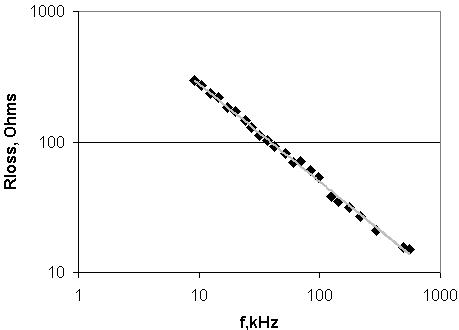
them A graph of loss resistance vs. frequency (see attachment for
one on log axes) shows Rloss is very roughly inversely
proportional to frequency. The curve-fitting function of the
spreadsheet software produced the line linking the points - this
gives the formula:
Rloss(ohms) = 1550 x 1/(f, kHz)^0.75
I think the slight kinks in the graph are due to using different loading
coils with different distributed capacitance to ground. I found the
capacitance of my TX loading coils to ground was about 30pF, so
a significant fraction of the antenna capacitance is that of the
loading coil, and changing the voltage distribution on the loading
coil will presumably alter the antenna loss resistance a bit.
The antenna handbooks say that the antenna losses of typical
(commercial) LF antennas increase with frequency, while this one
does just the opposite. Other people have found the same thing
comparing 136k and 73k operation. I think this offers support for
the theory that the losses in amateur LF antennas are normally
dominated by dielectric losses. If the antenna was fed with a
constant current I, the voltage on the ant is close to V = I x Xc,
where Xc is the capacitive reactance, since the resistance is
much smaller than the reactance. Therefore V will be proportional
to Xc, which in turn is proportional to 1/f. The dielectric losses
increase roughly proportionaly to the frequency, but are also
proportional to V^2, and V decreases with frequency. So overall, if
all the resistance was due to dielectric loss, the loss resistance
would be proportional to 1/f. however, there are some additional
losses due to ground resistance, skin effect and so on, which
increase with frequency, leading to the overall 1/(f^3/4)
dependence.
The increasing capacitance at high frequencies is due to the
distributed inductance of the antenna wire; the inductive reactance
partially cancels the capacitive reactance, leading to a higher
effective capacitance (lower reactance) at higher frequency, as
the antenna gets nearer to it's resonant frequency.
It would be nice to try measuring some different antennas, to see if
the same effects occur generally - unfortunately, I only have the
one antenna at the moment! I would not be suprised if the loss
resistance was a funtion of a slightly different power of f with
different antenna geometries and environments.
Cheers, Jim Moritz
73 de M0BMU


-------------- Enclosure number 1 ----------------
* This message contains the file 'rloss.jpg', which has been
* uuencoded. If you are using Pegasus Mail, then you can use
* the browser's eXtract function to lift the original contents
* out to a file, otherwise you will have to extract the message
* and uudecode it manually.
|