Return to KLUBNL.PL main page

rsgb_lf_group
[Top] [All Lists]

Re: Re: LF: My transmit converter description

To: <[email protected]>
Subject: Re: Re: LF: My transmit converter description
From: "mal hamilton" <[email protected]>
Date: Tue, 5 Feb 2013 17:56:24 -0000
References: <CAKvcm2edSxcESuKJR6yux7M-pBXE63rUVPbE98M-L6Mb8--cLg@mail.gmail.com>, <[email protected]> <trinity-2a571214-eade-473f-9083-9b722b64042b-1360055582805@3capp-webde-bs04>
Reply-to: [email protected]
Sender: [email protected]

Victor
This is also my observation and except the swithing is spot on it wil just kill the PA FET
The Drain trailing edge needs to adjusted to eliminate voltage spikes and should appear rounded towards the next cycle.
g3kev
 
----- Original Message -----
Sent: Tuesday, February 05, 2013 9:13 AM
Subject: Aw: Re: LF: My transmit converter description

Hi Dimitros,
the pulse shape in this picture does not look good: http://people.physics.anu.edu.au/~dxt103/472/nltt/vk1sv-drain.jpg
The reason seams to be the duty cycle at the gate. Please try to change R5 to a 100k potentiometer and trim it to a clean single Pilse an the drain. I solved the same problem tha way in my PA, wich killed my IRF540.
Kind regards
Eike DL3IKE
PS: sorry for my english ;)
Gesendet: Dienstag, 05. Februar 2013 um 08:45 Uhr
Von: "Victor van Kooten" <[email protected]>
An: [email protected]
Betreff: Re: LF: My transmit converter description
Looks very nice Dimitris,hope to see/hear you soon,

73

Victor

>>> Dimitrios Tsifakis <[email protected]> 05/02/2013 01:50 >>>
Hello group,

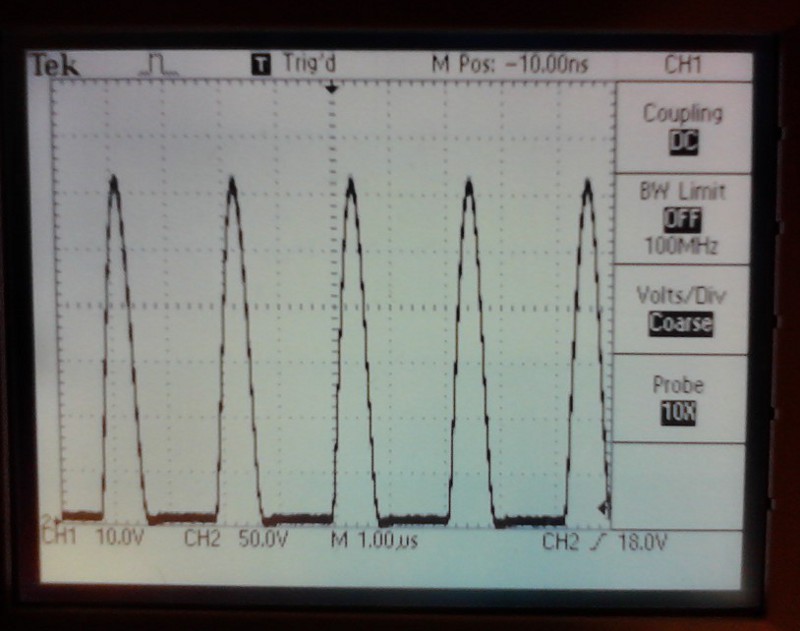
My transmit converter is now finished and tested - it survived two
sessions of 50% duty cycle WSPR transmissions on 475 kHz and the
results are great. I thought others may find this useful, so I have
put a write-up on my web page:

http://people.physics.anu.edu.au/~dxt103/472/nltt/

It is a 50 W class-e PA designed for 50 ohm impedance, so there is no
need for an impedance transformer. Doesn't get simpler than that :-)
The driving circuit is based on G3XBM Roger's design with the
difference of a 10 MHz OCXO LO and the addition of a beefy MOSFET
driver.

73, Dimitris VK1SV


<Prev in Thread] Current Thread [Next in Thread>